Your equipment works in dust, under shock loads, and in extreme heat. A standard bearing will fail quickly. You need a bearing engineered to be robust, to endure these punishing conditions without compromise.
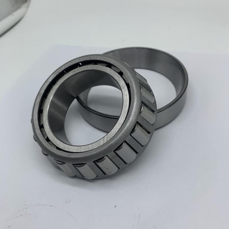
Robust tapered roller bearings for demanding environments feature enhanced designs like heavy-duty cages, specialized sealing, larger internal clearance (C4/C5), and high-grade or surface-treated steel. They are used in mining, construction, agriculture, and heavy processing where reliability under stress is critical.
"Robust" means more than just a thicker ring. It’s a holistic approach to surviving specific environmental and operational challenges. To specify the right robust bearing, you must understand its core applications, the critical clearance setting, how it differs from other heavy-duty options, and the broader family it belongs to.
What are tapered roller bearings used for?
In a demanding environment, forces are complex and unpredictable. Tapered roller bearings1 are chosen because their design inherently manages multiple types of stress, making them a fundamental component in the toughest machines on earth.
Tapered roller bearings1 are used to support high combined radial and axial loads in harsh applications like off-highway vehicle axles, mining conveyor drives, steel mill roll necks, heavy-duty gearboxes, and agricultural machinery. Their robust construction and adjustability make them ideal for environments with shock, vibration, and contamination.
Their use is dictated by their geometry. The conical rollers and raceways are the key to handling the complex force diagrams found in demanding settings.
Applications Where Robustness is Non-Negotiable
Let’s look at specific sectors where standard bearings fail and robust tapered rollers are the mandated solution.
1. Mining and Quarrying:
- Application: Crusher jaws, vibrating screens, conveyor head pulleys.
- Demands: Extreme shock loads, abrasive dust, constant vibration.
- Why Tapered Rollers: They handle the radial load of rocks and the axial thrust from uneven loading. Robust versions use sealed designs2 and hardened steel3 to resist abrasive wear.
2. Construction and Heavy Equipment:
- Application: Excavator swing circles, wheel loader axles, bulldozer final drives.
- Demands: High impact loads, exposure to mud and water, wide temperature swings.
- Why Tapered Rollers: Provide the load capacity for lifting and digging. Robust versions have enhanced sealing (triple-lip seals4) and corrosion-resistant coatings or stainless steel components.
3. Agriculture:
- Application: Tractor gearboxes, combine harvester axles, tillage equipment.
- Demands: Shock loads from uneven ground, exposure to crop debris, dust, and moisture.
- Why Tapered Rollers: Manage torque and weight loads. Robust versions focus on effective sealing to keep out chaff and dirt and use tough cages to handle shock.
4. Metal Processing (Steel Mills):
- Application: Rolling mill work roll necks.
- Demands: Incredible radial and axial forces, high temperatures, and water spray from cooling.
- Why Tapered Rollers: The only bearing type that can reliably take the combined rolling and separating forces. Robust versions use heat-stabilized steel5 and water-resistant seals.
My insight: A mining company in Chile operated a fleet of large haul trucks. The wheel bearings on these multi-ton vehicles were failing prematurely. The standard tapered roller bearings couldn’t handle the combination of extreme load, dirt ingress, and poor maintenance intervals. We worked with them to develop a robust specification: bearings with a C5 clearance6 (for heat and fit), integrated high-performance seals, and a special high-adhesion grease that wouldn’t wash out. We also supplied them in a pre-adjusted cartridge unit to eliminate installation errors. The bearing life increased by over 400%. The use was clear—support the truck’s weight and drive torque. The robust execution made it possible in that specific, brutal environment.
What is C1, C2, and C3 bearing clearance1?
In a demanding environment, heat and load are magnified. The internal clearance setting (C1, C2, C3, C4, C52) becomes a survival parameter. Choosing the standard C3 might be insufficient; robust designs often require stepping up to C4 or C5.
C1, C2, C3, C4, C52 are ISO standard radial internal clearance groups for bearings. C2 is tightest, CN (Normal) is standard, C3 is larger, and C4/C5 are larger still. For demanding environments, C4 or C5 clearance3 is typically specified to prevent seizure from high operational temperatures4, heavy interference fits, and shock loads that can distort components.
Clearance is the engineered safety gap. In harsh conditions, you need a bigger safety margin.
Why Larger Clearance (C4/C5) is Essential for Robustness
Standard clearance calculations assume moderate conditions. Demanding environments violate those assumptions.
1. The Harsh-Environment Clearance Squeeze:
Three factors aggressively reduce the initial clearance in tough applications:
- Severe Interference Fits: Heavy equipment often uses very tight press fits to prevent loosening under vibration. This significantly stretches the inner ring.
- High Operational Temperatures: Friction, ambient heat, or process heat (like in a steel mill) cause significant thermal expansion. The inner ring expands more than the housing.
- Load-Induced Deformation: Under extreme shock loads, the bearing rings can deform elastically, momentarily reducing internal space.
2. The Consequence: From Clearance to Catastrophe
If the initial clearance (e.g., C3) is completely taken up by these factors, the bearing operates at zero clearance or goes into preload. This causes:
- Massive increase in friction and heat.
- Rapid grease breakdown.
- Metal-to-metal contact and eventual seizure.
- This failure can happen in days or hours, not years.
3. Clearance Selection Guide for Demanding Duty:
| Clearance Group | Initial Clearance | Recommended for Demanding Environments? | Typical Robust Application |
|---|---|---|---|
| C2 / CN | Very Small / Standard | No. High risk of seizure. | Avoid. |
| C3 | Larger than Normal | Marginal. May be okay for less severe conditions or with perfect temperature control. | General industrial gearboxes in controlled settings. |
| C4 | Larger than C3 | Yes, Standard Robust Choice. Provides a reliable safety margin. | Mining equipment, heavy conveyors, off-road vehicle axles. |
| C5 | Very Large | Yes, for Extreme Conditions. For applications with known high heat or severe shock. | Steel mill roll necks, vibratory machinery, hot environment fans. |
Important Note: A bearing with C5 clearance may feel "loose" when you handle it cold. This is normal and correct. The looseness is the design margin that ensures it runs freely and reliably under operating conditions.
My insight: A sugar mill in Brazil had a persistent problem with the bearings on their large, steam-heated dryer drums. They used C3 clearance bearings. The bearings near the heat source would seize regularly. We measured the temperature gradient and calculated the differential expansion. It was clear C3 was inadequate. We switched them to C5 clearance bearings. The seizures stopped immediately. The mill manager was initially concerned about the perceived looseness, but the results proved the engineering. In demanding environments, the correct clearance is the cheapest insurance policy you can buy. Always err on the side of a larger clearance group when conditions are harsh.
What is the difference between cylindrical and tapered roller bearings?
Both are "heavy-duty" roller bearings. But in a demanding environment, using a cylindrical roller bearing where a tapered roller is needed is a guaranteed path to rapid, catastrophic failure. The difference is not minor; it’s fundamental to how they manage forces.
The core difference is load direction. Cylindrical roller bearings1 handle extremely high radial loads2 only and allow axial shaft movement. Tapered roller bearings3 handle high combined radial and axial loads4s](https://sdycbearing.com/2026/01/05/tapered-roller-bearings-engineered-for-superior-load-performance/)[^5] and provide rigid axial shaft location. In demanding environments with axial forces, tapered rollers are the necessary choice.
Choosing the wrong type because they look similar or are both "roller" bearings is a common and costly mistake.
A Side-by-Side Comparison for Harsh Applications
This table highlights why one succeeds and the other fails in specific demanding scenarios.
| Aspect | Cylindrical Roller Bearing | Tapered Roller Bearing |
|---|---|---|
| Primary Load | Pure Radial. Highest capacity for this. | Combined Radial and Axial. Excellent capacity for both. |
| Axial Load | Cannot handle (causes roller end against flange, leading to rapid wear and failure). Exceptions exist for flanged types (NJ/NUP) for limited one-direction load. | Specifically designed to handle high axial loads5 in one direction. Used in pairs for two-direction capability. |
| Axial Positioning | Allows free axial float. Used as a "non-locating" bearing. | Provides rigid axial location. Used as a "locating" bearing. |
| Typical Harsh App | Large dryer or kiln support rollers (pure weight, shaft expands). | Gearbox of a rock crusher (radial load from gears, axial thrust from helical teeth). |
| Failure Mode if Misapplied | If axial force is present, the roller ends grind against the flanges, generating metal debris and heat, leading to seizure. | If used where only pure radial load exists, it’s often overkill but will work. Its weakness is misapplication in very high-speed roles. |
Why Tapered Rollers are Preferred for Demanding, Combined-Load Applications:
In harsh environments, forces are rarely pure. A conveyor drive has radial load from belt tension and axial load from misalignment. A crusher has radial load from the material and axial thrust from the drive gears. A wheel loader axle has radial load from the vehicle’s weight and axial load during turning.
A cylindrical roller bearing in any of these applications would fail quickly because it has no proper mechanism to carry the axial component. The tapered roller bearing’s conical geometry is literally designed to resolve these combined forces into manageable components carried by the rollers and races.
My insight: A cement plant used cylindrical roller bearings on the pinion shaft of their large ball mill gearbox. The bearings failed every 6-8 months. The failure analysis6 showed severe wear on the roller ends and guide flanges—a classic sign of excessive axial load. The helical gears in the gearbox were generating axial thrust that the cylindrical bearings could not handle. The solution was not a bigger cylindrical bearing; it was a different type of bearing. We redesigned the housing to accept a matched pair of robust tapered roller bearings. The new bearings handled the combined radial and axial loads4s](https://sdycbearing.com/2026/01/05/tapered-roller-bearings-engineered-for-superior-load-performance/)[^5] seamlessly and lasted for years. The difference between the two types in a demanding setting is the difference between failure and success.
What are the three types of roller bearings?
When an engineer designs for a demanding environment, they have three primary roller bearing options in their toolkit. Each has a distinct strength. Knowing all three allows you to understand why tapered rollers are so often the choice for combined-load robustness.
The three primary types of roller bearings are cylindrical roller bearings1, tapered roller bearings2, and spherical roller bearings3. They are distinguished by roller shape: cylindrical for pure radial loads, tapered for combined loads4, and spherical for high radial loads with misalignment tolerance.
This categorization is based on core capability. For robustness, the question is: "What is the primary challenge my bearing must overcome?"
Choosing the Right Type for Specific Harsh Conditions
Here’s how an engineer matches the bearing type to the environmental and operational demand.
| Bearing Type | Roller Shape | Signature Robustness Trait | Demanding Environment Where it Excels | Where it Fails |
|---|---|---|---|---|
| Cylindrical Roller | Straight cylinders | Ultimate Radial Load Strength. Simplicity. | Applications with immense, pure radial load and precise alignment. E.g., large rotary kiln support rollers. | Any significant axial load or misalignment. |
| Tapered Roller | Truncated cones | Combined Load & Adjustability. Provides system rigidity5. | Environments with shock, combined loads4, and need for precise axial control. E.g., off-road vehicle axles, rolling mills, heavy gearboxes. | Extremely high-speed applications (friction/heat). |
| Spherical Roller | Barrel-shaped | Self-Alignment & Shock Absorption. Forgiving of installation errors and frame deflection. | Environments with severe misalignment, very high radial load, and heavy vibration. E.g., vibrating screens, mining shovels, paper mill rolls. | Applications requiring very precise axial shaft location. |
The Niche for Robust Tapered Roller Bearings:
Among these three, robust tapered rollers fill a critical niche. They are the go-to choice when the demanding environment presents BOTH:
- High combined loads4 (radial + axial), AND
- A requirement for system rigidity5 and precise shaft positioning.
Spherical rollers might handle misalignment better, but they allow more axial "float." Cylindrical rollers handle higher pure radial loads, but they cannot take axial force. The tapered roller is the compromise that delivers on both fronts with great strength, which is exactly what many heavy machines need.
Beyond the Basic Three:
For extreme robustness, variations exist within each type. For tapered rollers, this means:
- Increased wall thickness for higher load capacity.
- Special cage designs (machined brass, pin-type) for higher shock resistance.
- Enhanced sealing systems (Triple-lip seals, labyrinth designs).
- Surface treatments (phosphating, black oxide) for run-in and corrosion resistance.
My insight: On a visit to a port handling bulk minerals, I saw all three types. The spherical rollers were on the stacker-reclaimer booms (huge loads, constant misalignment). The cylindrical rollers were on the rotary ship loader’s main slew ring (pure radial load). The tapered rollers were everywhere in the drive gearboxes of the conveyors and the wheel bogies of the massive machines. The chief engineer explained: "For any driveline that transmits torque and has gears, we use tapered rollers. They take the push and pull from the gears and hold everything tight. We use the toughest specs we can get." Robust tapered rollers aren’t just a bearing; they are the linchpin of power transmission in the world’s toughest workplaces.
Conclusion
Specifying robust tapered roller bearings for harsh conditions requires understanding their combined-load capability, selecting larger clearance (C4/C5), recognizing their distinct advantage over cylindrical types, and knowing their place within the heavy-duty roller bearing family.
-
Explore this link to understand the unique features and applications of cylindrical roller bearings in various industries. ↩ ↩ ↩ ↩ ↩
-
Discover the benefits of tapered roller bearings and why they are preferred in demanding environments. ↩ ↩ ↩ ↩ ↩
-
Learn about the applications and advantages of spherical roller bearings in handling misalignment. ↩ ↩ ↩ ↩
-
Understanding combined loads is crucial for selecting the right bearing; this resource provides in-depth insights. ↩ ↩ ↩ ↩ ↩ ↩ ↩
-
Explore how system rigidity impacts bearing performance and why it’s essential in engineering design. ↩ ↩ ↩ ↩
-
Delve into failure analysis to learn how to prevent bearing failures and improve machinery reliability. ↩ ↩