
Your spherical roller bearing fails after just weeks of operation. The bearing itself is high quality. The load is within limits. The lubrication is correct. The hidden culprit is often the shaft and housing tolerances—the invisible gap or interference that dictates how the bearing functions.
Shaft and housing tolerances critically impact spherical roller bearing performance by controlling the bearing’s internal clearance after mounting, ensuring proper load distribution, and preventing creeping (slippage) of rings. Incorrect tolerances can lead to excessive heat generation, premature fatigue, fretting corrosion, and catastrophic failure. Proper fit selection is essential for achieving the bearing’s designed life.
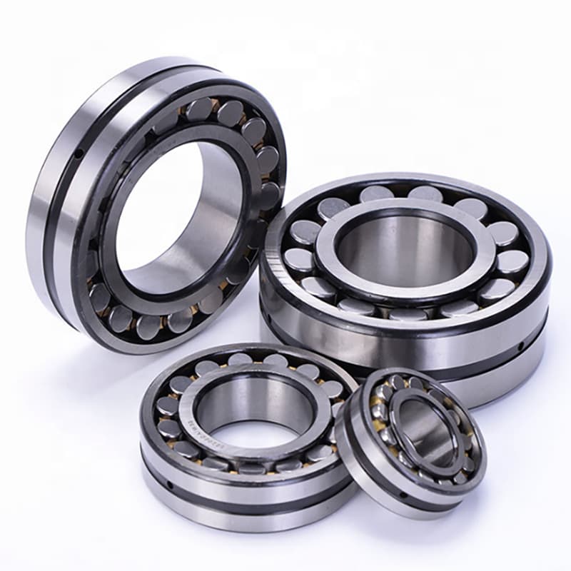
In my years of manufacturing spherical roller bearings for heavy industries like mining, steel, and cement, I have seen how a perfectly good bearing can be destroyed by a shaft that is just a few micrometers too large or too small. The bearing doesn’t fail because it’s weak. It fails because the system around it is wrong. Let’s explore how to specify shaft tolerances, determine correct fits, understand shaft and bush clearances, and know exactly how much space should exist between a bearing and its shaft.
How to give tolerance for shaft?
You are designing a shaft for a spherical roller bearing1. The bearing bore is 100mm. You know the shaft should be "a little bigger" than the bearing bore for a tight fit. But "a little" is not engineering. You need a precise specification.
To give a shaft tolerance2 for a spherical roller bearing1, you must first determine the required fit type (interference, transition, or clearance) based on the application’s load and rotation conditions. Then, you select a tolerance class3 from ISO standards4 (e.g., h6, j6, k6, m6, n6, p6) that provides the desired interference or clearance when combined with the bearing’s bore tolerance (e.g., 0 to -0.020mm for a P0 class bearing). The shaft diameter is then specified as, for example, "100mm k6" which defines an upper and lower limit (e.g., +0.025mm / +0.003mm).
This looks complex, but it follows a logical system. Let’s break it down step by step.
A Practical Guide to Specifying Shaft Tolerances
Step 1: Understand the Bearing’s Bore Tolerance.
Every bearing is manufactured with a tolerance on its bore diameter. For a standard P0 class bearing, the bore is always on the minus side of the nominal size. For a 100mm bore bearing, the actual bore might be anywhere from 100.000mm down to 99.980mm (a tolerance of 0 to -0.020mm). This means the bearing bore is always exactly at nominal or slightly smaller—never larger.
Step 2: Determine the Required Fit Type.
The fit depends on how the bearing ring rotates relative to the load.
| Condition | Fit Type Required | Why |
|---|---|---|
| Rotating inner ring (shaft rotates, load direction fixed) | Interference fit (tight fit) | Prevents the inner ring from creeping (rotating slowly) on the shaft, which causes fretting wear. |
| Stationary inner ring (shaft is stationary, load rotates) | Clearance or transition fit (looser fit) | Allows for easier assembly and disassembly. The ring doesn’t need to be tight because it doesn’t rotate relative to the load. |
| Heavy shock loads or thin-walled housing | Heavier interference | Extra tightness ensures the ring doesn’t move under extreme conditions. |
Step 3: Select the Tolerance Class.
ISO standard shaft tolerance2s are denoted by a letter (lowercase for shafts) and a number. The letter indicates the position of the tolerance zone relative to nominal. The number indicates the width of the zone (grade of accuracy).
| Common Shaft Tolerances for Spherical Roller Bearings | Fit Type | Typical Application |
|---|---|---|
| g6 | Clearance fit | Inner ring needs to slide on shaft (rare for spherical roller bearing1s). |
| h6 | Transition fit (close to nominal) | Light loads, inner ring can be moved with light force. |
| j6, k6 | Light interference fit5 | Normal loads, rotating inner ring. Most common for general applications. |
| m6, n6 | Interference fit | Heavy loads, shock loads, where a tight grip is essential. |
| p6 | Heavy interference fit5 | Very heavy loads, thin-walled hubs, requires heating for assembly. |
Step 4: Specify the Shaft Diameter.
For a 100mm shaft with a k6 tolerance, you would specify: "100mm k6". This means:
- Upper deviation: +0.025mm (shaft can be up to 100.025mm)
- Lower deviation: +0.003mm (shaft must be at least 100.003mm)
When this shaft is paired with a bearing bore of 100.000mm to 99.980mm, the resulting fit is always an interference (the shaft is always larger than the bore).
Step 5: Communicate Clearly on Drawings and Orders.
On your engineering drawing, write: "Shaft diameter 100 k6" and include the limit dimensions. When ordering a custom shaft from a machine shop, provide both the nominal size and the tolerance class3.
My Insight from Manufacturing:
In our factory, we often receive shafts from clients for custom bearing applications. We measure them. A surprising number are out of tolerance. The most common error is making the shaft too tight (too large) for a k6 specification, thinking "tighter is better." It’s not. Too much interference can remove all internal clearance from the bearing, causing it to overheat and seize. Giving the correct tolerance is not just about following a standard. It’s about understanding the mechanical consequence. For a distributor like Rajesh, knowing these basics helps him advise his customers. When a customer complains of a hot bearing, he can ask, "What was your shaft tolerance2?" This question often uncovers the root cause.
How to determine bearing shaft and housing fit?
You have the bearing and the machine design. You need to choose the right fit for both the shaft and the housing. Guessing leads to failure. There is a systematic method based on international standards and application conditions.
To determine bearing shaft and housing fit, follow this process: 1) Identify the type of rotation (which ring rotates relative to the load). 2) Assess the magnitude of the load (light, normal, heavy, shock). 3) Consider the shaft and housing material and design (solid or thin-walled). 4) Consult bearing manufacturer catalogs1 or ISO standards2 (ISO 286) which provide recommended fit tables based on these conditions. The result is a specific tolerance class3 for the shaft (e.g., k6, m6) and the housing bore (e.g., H7, J7, M7).
This is not guesswork. It is a structured decision based on decades of engineering experience codified into standards.
A Step-by-Step Fit Selection Process
Step 1: Determine Rotation Condition (The Most Important Factor).
This decides whether the fit needs to be tight or loose.
| Condition | Ring that Moves | Fit Required on That Ring | Fit on the Other Ring |
|---|---|---|---|
| Rotating shaft (inner ring rotates) | Inner ring | Interference fit (tight) | Clearance or transition fit (looser) |
| Rotating housing (outer ring rotates) | Outer ring | Interference fit (tight) | Clearance or transition fit (looser) |
| Load direction rotates (e.g., unbalanced rotor) | Both rings may be loaded in a way that requires tight fits on both. | Special consideration needed. |
Step 2: Assess Load Magnitude.
Manufacturers classify loads relative to the bearing’s basic dynamic load rating (C).
- Light Loads: P ≤ 0.07 C
- Normal Loads: 0.07 C < P ≤ 0.15 C
- Heavy Loads: P > 0.15 C (or shock loads)
Heavier loads require tighter interference fit4s to prevent the ring from creeping.
Step 3: Consider Shaft and Housing Design.
- Solid Shafts: Standard tolerance recommendations apply.
- Hollow Shafts: Require tighter interference because they are more flexible.
- Thin-Walled Housings: Also require tighter fits to prevent distortion.
Step 4: Use Manufacturer’s Tables.
Bearing catalogs (SKF, FYTZ, etc.) provide detailed fit recommendation tables5. Here is a simplified example for rotating inner ring conditions on a solid steel shaft:
| Load Condition | Shaft Diameter (mm) | Recommended Shaft Tolerance | Example Application |
|---|---|---|---|
| Light loads (P ≤ 0.07C) | All sizes | j6 or k6 | Conveyor rollers, light fans |
| Normal loads (0.07C < P ≤ 0.15C) | Up to 100mm | k6 | General gearboxes, pumps |
| Over 100mm | m6 | ||
| Heavy or shock loads (P > 0.15C) | Up to 100mm | m6 | Crushers, vibrating screens |
| Over 100mm | n6 or p6 |
For housing fits with a rotating inner ring (stationary outer ring), the outer ring usually requires a looser fit:
| Housing Condition | Recommended Housing Tolerance | Example |
|---|---|---|
| Split housing (typical) | H7 | Standard for most applications |
| Solid housing, light loads | J7 | For easier disassembly |
| Thin-walled housing or high temperatures | M7 or N7 | Tighter fit to prevent outer ring movement |
Step 5: Calculate Resulting Fit Range.
Once you have the shaft tolerance (e.g., k6) and the bearing bore tolerance (P0 class), you can calculate the range of possible interference. For a 100mm bearing:
- Bearing bore: 100.000mm to 99.980mm
- Shaft k6: 100.025mm to 100.003mm
- Resulting fit: Minimum interference = 100.003 – 100.000 = 0.003mm. Maximum interference = 100.025 – 99.980 = 0.045mm.
This range ensures a consistent tight fit.
My Insight on Fit Selection for Spherical Roller Bearings:
Spherical roller bearings are often used in heavy, demanding applications. In my experience, underestimating the required interference is a common mistake. A client might use a k6 fit for a crusher bearing when an m6 or n6 is needed. The result is a bearing that creeps on the shaft, causing fretting wear and premature failure. When we receive failed bearings for analysis, the telltale sign of a loose fit is a polished, shiny ring on the shaft contact area. The best practice is to be conservative. If there is any doubt, choose the next tighter fit. It’s easier to heat a bearing to mount it on a slightly tighter shaft than to deal with a bearing that spins on its seat.
What is the tolerance for shaft and bush?
You are working with plain bearings1 (bushes), not rolling bearings. The principles are similar, but the numbers are different. A bush relies on a film of lubricant, so the clearance2 is much larger and more critical.
For a shaft and bush (plain bearing) combination, the tolerance is designed to create a specific clearance2 (not interference) to allow for a lubricant film3. Common tolerance combinations are H7/f74 or H7/g6 for general applications, where the housing (or bush OD) is H7, the bush bore is typically finished to size, and the shaft is f7 or g6. This provides a controlled clearance2 that ensures hydrodynamic lubrication without excessive play.
This is a completely different world from rolling bearings. The shaft must float on a film of oil.
Understanding Plain Bearing Tolerances
1. The Fundamental Difference:
- Rolling Bearings: Rely on interference fits to prevent movement between rings and shafts/housings. The rolling elements provide the motion.
- Plain Bearings (Bushes): Rely on a precise clearance2 between the shaft and the bush bore. The shaft slides directly on a lubricant film3 within the bush. Too little clearance2 causes seizure. Too much causes vibration and loss of oil pressure.
2. Common Tolerance Systems:
The ISO system for clearance2s uses shaft and hole tolerances that ensure a gap.
| Component | Typical Tolerance | Explanation |
|---|---|---|
| Housing bore (for press-fit bush) | H7 | Standard tolerance for housing that will receive a press-fit bush. |
| Bush OD | r6 or p6 | Interference fit to hold bush securely in housing. |
| Bush ID (after installation) | Finished to size, often with an F7 or G7 tolerance internally. | This is the working surface. The bush may be machined after pressing to achieve the correct final diameter. |
| Shaft | f7 or g6 | Provides the clearance2 with the bush ID. f7 is a common "running fit." |
3. Resulting Clearance Examples:
For a 50mm shaft and bush:
- Bush ID tolerance (e.g., F7): +0.025mm / +0.050mm (meaning 50.025mm to 50.050mm)
- Shaft tolerance (e.g., f7): -0.025mm / -0.050mm (meaning 49.975mm to 49.950mm)
- Resulting clearance2: Minimum = 50.025 – 49.950 = 0.075mm. Maximum = 50.050 – 49.975 = 0.075mm? Wait, this needs correction. Let’s do a proper example:
A more typical combination is H7/f74 for a general clearance2 fit:
- Hole (bush ID after installation) H7: for 50mm, +0.025mm / 0mm (50.000mm to 50.025mm)
- Shaft f7: for 50mm, -0.025mm / -0.050mm (49.975mm to 49.950mm)
- Resulting clearance2: Minimum = 50.000 – 49.950 = 0.050mm. Maximum = 50.025 – 49.975 = 0.050mm? This gives a consistent clearance2 around 0.05mm.
The actual numbers depend on the specific tolerance grades chosen.
4. Factors Affecting Clearance Selection:
- Shaft Speed: Higher speeds generally require larger clearance2s to accommodate heat expansion and maintain oil film.
- Load: Heavier load5s require larger clearance2s to maintain oil film thickness under pressure.
- Lubricant Viscosity: Thicker oils can work with larger clearance2s.
- Material: Different bearing material6s (bronze, Babbitt, polymer) have different thermal expansion rates.
Comparison Table: Rolling Bearing Fit vs. Plain Bearing Fit
| Feature | Rolling Bearing (Spherical Roller) | Plain Bearing (Bush) |
|---|---|---|
| Fit on shaft | Interference (tight) | Clearance (loose) |
| Typical shaft tolerance | k6, m6, n6 (plus side) | f7, g6 (minus side) |
| Resulting gap | 0 to 0.05mm interference | 0.05 to 0.15mm clearance2 |
| Purpose of fit | Prevent ring creep | Allow oil film formation |
| Lubrication | Grease or oil, film not essential for fit | Oil film is essential for operation |
My Insight on the "Shaft and Bush" Question:
This question sometimes comes from clients who are new to bearings or who are mixing terminology. If a client asks me about "shaft and bush tolerance" while discussing spherical roller bearings, I know they may be confusing two different technologies. It’s important to clarify: for rolling bearings, we want the shaft to be tight inside the bearing (interference). For bushes, we want a precise gap. Using the wrong philosophy leads to immediate failure. In our export markets, we often provide basic technical clarification along with our products. This helps buyers like Rajesh serve their customers better by ensuring they use the right components with the right understanding.
How much clearance between bearing and shaft?
You are assembling a spherical roller bearing onto a shaft. You wonder how much space should exist. Should it slide on easily? Should it require force? The answer depends on the type of fit you need.
For a spherical roller bearing where the inner ring rotates (the most common case), there should be zero clearance1—in fact, there should be interference. The shaft should be slightly larger than the bearing bore, requiring the bearing to be heated or pressed onto the shaft. For stationary inner ring2 applications, a small clearance of 0 to 0.02mm may be acceptable. For plain bearings3 (bushes), a clearance of 0.05mm to 0.15mm is typical depending on size and application.
The answer is not a single number. It depends entirely on the application.
Quantifying the "Clearance" (or Interference) for Different Scenarios
1. For Rotating Inner Ring (Standard Case):
The goal is zero relative motion between the shaft and the bearing inner ring. This is achieved by an interference fit4.
| Bearing Bore Size | Typical Interference (for k6/m6 fit) | Assembly Method |
|---|---|---|
| Up to 50mm | 0.002mm to 0.025mm | Light press or bearing heater5 (80-100°C) |
| 50mm to 100mm | 0.003mm to 0.045mm | Bearing heater required |
| 100mm to 200mm | 0.005mm to 0.060mm | Induction heater or oil bath |
| Over 200mm | 0.010mm to 0.080mm | Special heating and mounting tools |
Note: These are interferences, meaning the shaft is larger than the bore. There is no "clearance" in the traditional sense.
2. For Stationary Inner Ring (Less Common):
Here, a small clearance may be acceptable or even desirable to allow for easier axial adjustment.
| Condition | Typical Clearance | Fit Type |
|---|---|---|
| Light loads, easy assembly needed | 0 to 0.015mm | Transition fit (h6, j6) |
| Non-rotating inner ring, load is rotating | 0.010mm to 0.030mm clearance | g6 or f6 (rare for spherical roller bearings) |
3. For Plain Bearings (Bushes):
Here, clearance is essential and much larger.
| Shaft Diameter | Typical Diametral Clearance (for general engineering) | Example Fit |
|---|---|---|
| 20mm | 0.020mm to 0.060mm | H7/f7 |
| 50mm | 0.050mm to 0.100mm | H7/f7 |
| 100mm | 0.070mm to 0.150mm | H7/f7 or H7/e8 |
| 200mm | 0.100mm to 0.250mm | H7/e8 |
4. How to Measure and Verify:
- For Interference Fits: You don’t measure the assembled clearance (there is none). You measure the shaft and bearing bore separately before assembly to ensure they are within tolerance.
- For Clearance Fits: After assembly, you may be able to feel a slight rock. For precision work, use a feeler gauge6 or dial indicator to measure the movement.
5. The Consequence of Getting It Wrong:
| Problem | Symptom | Result |
|---|---|---|
| Too much interference | Bearing is hard to turn after mounting. | Internal clearance is reduced to zero or negative. Bearing overheats and seizes. |
| Too little interference (clearance) | Bearing creeps on shaft. | Fretting wear, polishing of shaft, vibration, noise, eventual failure. |
| Too much clearance (plain bearing) | Shaft rattles, oil pressure drops. | Loss of oil film, metal-to-metal contact, rapid wear. |
| Too little clearance (plain bearing) | Shaft binds, overheats. | Seizure, scoring of shaft and bush. |
My Insight on the "How Much Clearance" Question:
This is one of the most common questions from maintenance teams. The answer is almost always a surprise: "For a rolling bearing on a rotating shaft, you want zero clearance1—actually, you want the shaft to be bigger than the bearing." This concept is counterintuitive to someone used to sliding fits. In our training for distributors like Rajesh, we emphasize this point. When his customers call with a hot bearing, the first question should be: "How did the bearing fit on the shaft? Did you have to tap it on, or did it slide easily?" If it slid easily, that’s likely the problem. Understanding this single concept—interference for rotating rings—prevents countless failures. The clearance (or lack thereof) between bearing and shaft is not a variable to be guessed. It is a precisely engineered specification that must be followed.
Conclusion
Shaft and housing tolerances are fundamental to spherical roller bearing performance. Correct interference fits for rotating inner rings prevent creep and failure. Using ISO tolerance classes like k6, m6, and n6, and understanding when to apply them, ensures your bearings achieve their full design life. Always specify, measure, and verify these critical dimensions.
-
Understanding zero clearance is crucial for ensuring proper fit and function in bearing applications. ↩ ↩ ↩ ↩ ↩ ↩ ↩
-
Learn about stationary inner rings and their implications for bearing assembly and performance. ↩ ↩ ↩ ↩ ↩ ↩ ↩ ↩ ↩ ↩ ↩ ↩ ↩ ↩ ↩ ↩ ↩ ↩ ↩ ↩
-
Discover the unique characteristics of plain bearings and how clearance impacts their operation. ↩ ↩ ↩ ↩ ↩ ↩
-
Explore the concept of interference fit to grasp how it affects bearing performance and longevity. ↩ ↩ ↩ ↩ ↩
-
Learn how bearing heaters facilitate assembly and ensure proper interference fits. ↩ ↩ ↩ ↩ ↩
-
Using a feeler gauge is essential for precise measurement in bearing assembly, ensuring optimal fit. ↩ ↩