
Your machinery faces heavy loads and tough conditions every day. A bearing failure means costly downtime. You need bearings built for endurance, not just basic function.
For durable performance, explore tapered roller bearings known for handling high combined radial and axial loads. Our range includes standard and precision grades (P5/P6), various clearance options (C3, C4), and robust designs suitable for automotive, industrial, and heavy machinery applications, ensuring long service life.
Durability isn’t an accident; it’s engineered. To choose the right durable tapered roller bearing, you need to understand what they are, how to verify their critical setup, how to identify them, and the geometry that gives them strength. This guide will help you navigate our product range with confidence.
What are tapered roller bearings?
You need a bearing that can take a beating from all directions. Tapered roller bearings1 are engineered for exactly that. They are not just another type of bearing; they are a solution for complex load situations where durability is key.
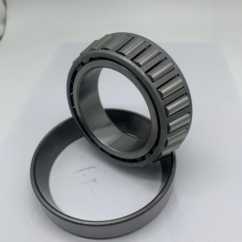
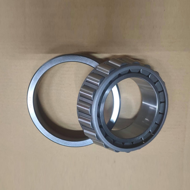
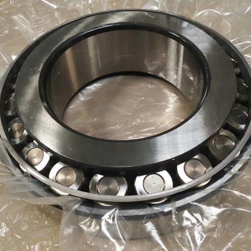
Tapered roller bearings1 are rolling element bearings with conical rollers and raceways. This design allows them to efficiently support high combined radial (perpendicular to the shaft) and axial (parallel to the shaft) loads simultaneously, making them exceptionally durable for demanding applications like gearboxes and wheel hubs.
Their unique construction is the source of their strength and versatility. Let’s break down the components and how they work together to create durability.
The Components of Durability: Inside a Tapered Roller Bearing
A tapered roller bearing is a system. Each part plays a specific role in ensuring long life under load.
1. Core Components and Their Functions:
- Cone (Inner Ring): This is the part pressed onto the shaft. It has a conical raceway and a large guiding rib (back face rib) that keeps the rollers aligned.
- Cup (Outer Ring): This ring fits into the housing. It also has a conical raceway.
- Tapered Rollers: These are the rolling elements. Their conical shape means they are designed to roll perfectly on the angled raceways without sliding. This minimizes wear.
- Cage (Retainer)2: This holds the rollers evenly spaced and guides them. For durable applications, cages are made of pressed steel, machined brass, or polyamide—each offering different benefits for shock resistance and speed.
2. The Secret to Combined Load Capacity:
The cone angle (the angle of the roller/raceway taper) is key. This angle allows the bearing to resolve any radial force into two components: one perpendicular to the shaft (carried radially) and one parallel to the shaft (carried as axial thrust against the cone’s large rib). This is why a single row can handle substantial axial load in one direction.
3. Paired for Performance and Durability:
Tapered roller bearings1 are almost always used in pairs (either back-to-back or face-to-face arrangement). This allows them to handle axial loads in both directions and provides rigid support for the shaft. This paired, adjustable system is a major factor in their durability and precision in applications like machine tool spindles or automotive differentials.
Our Range’s Durability Features:
When we talk about our durable range, we mean bearings with:
- High-Cleanliness Steel: To prevent premature fatigue from inclusions.
- Optimized Heat Treatment: For a hard, wear-resistant surface and a tough core to absorb shock.
- Robust Cage Options: Including reinforced steel cages for heavy shock loads.
- Precision Grinding: For smooth raceways that distribute load evenly and run cool.
My insight: A client in the mining sector in South Africa was using a competitor’s standard tapered roller bearing in a conveyor drive. They failed every 9 months from spalling. We analyzed the failure. The load was within rating, but the shock from starting under load was severe. We supplied a bearing from our heavy-duty series3, which used a special carburizing heat treatment4. This created a tougher core material that could better absorb the shock impacts, while the surface remained hard for wear resistance. The bearing life exceeded 2 years. The bearing type was the same, but the internal material specification within our range delivered the durability they needed. A "tapered roller bearing" is a category; our job is to provide the specific variant within that category that solves the durability challenge.
How to check taper roller bearing clearance?
Incorrect clearance is a leading cause of premature bearing failure. Too little clearance causes overheating and seizure. Too much clearance causes noise, vibration, and impact damage. Checking and setting it correctly is a fundamental skill for ensuring durability.
To check tapered roller bearing clearance1, mount the bearing pair2 in their housing with the shaft. Use a dial indicator3 to measure the shaft’s axial end-play4. The specific acceptable range depends on the bearing size and application, but a typical setting for industrial gearboxes5 is between 0.05mm to 0.15mm of axial play.
Checking clearance is about verifying the bearing’s internal space after it’s installed. This is different from the "C" code (like C3), which is the clearance before installation.
A Step-by-Step Guide to Axial End-Play Measurement
This is the practical method used by maintenance technicians and engineers to ensure a durable setup.
1. The Principle:
Tapered roller bearing clearance is expressed and set as axial end-play4 (or preload6). When you adjust the axial position of one bearing relative to its paired bearing, you directly control the internal radial clearance of both.
2. Tools You Will Need:
- Dial Indicator with magnetic base.
- Setup with the bearing pair2 installed in their housing, with the shaft in place and the adjusting nut(s) loosely fitted.
3. The Measurement Procedure:
- Mount the Dial Indicator: Fix the indicator’s base to the stationary housing. Position the indicator’s plunger against a fixed point on the shaft end, parallel to the shaft axis.
- Zero the Indicator: Gently push the shaft fully in one axial direction and set the dial to zero.
- Measure the Play: Pull the shaft firmly in the opposite axial direction. Read the total travel on the dial indicator3. This is the axial end-play4.
- Adjust: If the play is outside the recommended range, loosen the lock nut, turn the adjusting nut to move the bearing, re-tighten, and re-measure. Repeat until the desired end-play is achieved.
| 4. Understanding Clearance Settings for Durability: | Setting Type | Axial End-Play | Purpose & Effect | Typical Application |
|---|---|---|---|---|
| Running Clearance | Positive play (e.g., 0.05-0.15mm). | Allows for thermal expansion, ensures rollers are not overloaded. Prevents overheating. | Most industrial applications (gearboxes, conveyors). Maximizes durability and life. | |
| Preload | Zero or negative play. Bearings are slightly compressed. | Increases system rigidity, reduces shaft deflection under load. Increases accuracy but also friction and heat. | Machine tool spindles, high-precision applications where rigidity is paramount. | |
| Excessive Clearance | Large play (>0.25mm). | Causes noise, vibration, and allows impact loads on rollers. Greatly reduces life. | Undesirable. Result of wear or incorrect setting. |
My insight: A power generation plant in Indonesia had persistent failures on the fan drive gearboxes. They set the tapered roller bearings by "feel" and torque. We conducted training and found their end-play was often less than 0.01mm—essentially preload6ed. The gearboxes ran hot. We provided them with dial indicator3s and a specification sheet showing the required 0.08-0.12mm end-play for their bearing size. After they started measuring and setting correctly, the gearbox operating temperature dropped by 15°C, and bearing life doubled. Checking and setting the clearance is the single most important thing you can do to ensure the durability of a tapered roller bearing installation. It turns a quality component into a reliable system.
How to find taper roller bearing1g number](https://sdycbearing.com/2026/01/04/how-to-read-deep-groove-ball-bearing-codes-and-suffixes-as-a-buyer/)[^2]?
You have a failed bearing in hand, or you need to order a replacement. The bearing number2 is its unique identifier. Finding and interpreting it correctly is the only way to ensure you get an exact, durable replacement from our range.
To find the taper roller bearing1g number](https://sdycbearing.com/2026/01/04/how-to-read-deep-groove-ball-bearing-codes-and-suffixes-as-a-buyer/)[^2], look for markings stamped on the face of the cone (inner ring) or the cup (outer ring). Common number series include 30206, 32210, 32308, etc. The number indicates the bearing type, size series, and bore diameter. If worn off, use calipers to measure the bore, OD, and width and cross-reference with a dimension table.
The number is a code. Decoding it gives you all the key dimensions needed to find a match in our catalog or any standard catalog.
Decoding the Taper Roller Bearing Numbering System
Most tapered roller bearings follow the metric ISO standard numbering system3. Here’s how to read it.
1. Breaking Down a Common Number: Example 32210
- First Digit(s) – Type and Series:
- 3: This usually indicates a taper roller bearing1 according to ISO.
- 22: This is the dimension series4. It describes the bearing’s proportions.
- First digit (2): Width series – Medium width.
- Second digit (2): Diameter series – Light/Medium outer diameter.
- Sometimes, the first two digits are combined. For example, a "30306" bearing: The "3" indicates tapered, and "03" is the dimension series4.
- Last Two Digits – Bore Code:
- 10: For numbers 04 and above, multiply by 5 to get the bore diameter in mm.
- *10 5 = 50 mm bore.**
2. What if the Number is Worn Off? (The Measurement Method)
If no number is visible, you must measure.
- Measure the Bore (d): Use an internal caliper on the cone’s inside diameter.
- Measure the Outer Diameter (D): Measure the cup’s outside diameter.
- Measure the Widths: Measure the width of the cone (B) and the cup (C).
- Cross-Reference: Use these dimensions with a standard bearing dimension table (like ISO 355) or our online catalog to find the matching standard number.
3. Beyond the Base Number: Important Suffixes
The stamped number might be followed by suffixes that are crucial for durability. You must note these or specify them when ordering.
- Clearance Suffix: /C3, /C4 (e.g., 32210/C3).
- Precision Class Suffix: P6, P5 (e.g., 32210 P6).
- Cage Design Suffix: M – Brass cage; J – Pressed steel cage.
- Special Design Suffixes: May indicate enhanced features for durability.
Our Service: At FYTZ, we can help. You can send us clear photos of the bearing and its markings, along with your measurements. Our technical team will identify it and provide the correct part number from our range, ensuring you get a durable, direct replacement.
My insight: An agricultural machinery repair shop in Brazil sent us a worn bearing. The number was partially stamped: "3??12". They measured: ~60mm bore, ~110mm OD. They assumed it was a 30212. We asked for a photo. The cup width was much larger than a 30212 cup. Based on the proportions, we identified it as a 32212 bearing. The 322 series has a much higher load capacity than the 302 series. Installing a 30212 as a replacement would have failed quickly under the heavy load of the farm equipment. The correct identification ensured they received a bearing from our range with the durability the application demanded. Guessing a bearing number2 is risky; measuring and expert verification are essential.
What is a tapered roller bearing geometry?
The durability of a tapered roller bearing is rooted in its geometry—the specific angles, curvatures, and profiles of its components. This isn’t just about making a cone; it’s about precision engineering that optimizes load distribution, minimizes stress, and controls lubrication.
Tapered roller bearing geometry1 refers to the precise angles and profiles of its components: the contact angle between the roller and raceway, the roller profile (logarithmic or modified), the raceway curvatures, and the guiding rib design. This geometry determines load capacity, stress distribution, friction, and ultimately, the bearing’s durability and performance limits.
Advanced geometry is what separates a standard bearing from a high-performance, durable one. Manufacturers like us invest heavily in optimizing these invisible details.
The Key Geometric Parameters and Why They Matter
Let’s explore the main geometric features that engineers design for durability.
- What it is: The angle between a line perpendicular to the bearing axis and the line of contact between the roller and the raceway.
- Why it matters for durability: A larger contact angle increases axial load capacity but decreases radial capacity for a given size. It’s a fundamental design choice. Our range includes bearings with different contact angles for different applications (e.g., steeper angles for wheel bearings where axial loads from cornering are high).
2. Roller Profile3:
- What it is: The shape of the roller along its length. It is not a perfect straight cone.
- Why it matters for durability: A straight profile would cause edge stress at the ends of the contact patch. Modern bearings use a slightly curved (logarithmic or crowned) profile. This allows for slight misalignment and, crucially, distributes the load evenly along the roller’s length, preventing stress concentrations that lead to early fatigue. Our precision grinding processes ensure this profile is accurate.
3. Raceway Curvature and Crowning4:
- What it is: The raceways are also profiled to match the roller profile.
- Why it matters for durability: Proper matching ensures optimal hertzian contact stress distribution. Incorrect curvature leads to high edge stresses, dramatically reducing bearing life.
4. Rib Geometry5 (on the Cone):
- What it is: The design of the large rib that guides the roller ends.
- Why it matters for durability: The rib-roller end contact is a sliding contact, a potential source of heat and wear. Optimized rib geometry and surface finish, along with proper lubrication, minimize friction here. A durable bearing has a well-finished, robust rib.
| How Our Manufacturing Ensures Durable Geometry: | Geometric Feature | Potential Problem if Poor | Our Manufacturing Control for Durability |
|---|---|---|---|
| Contact Angle Consistency | Uneven load sharing among rollers. | Precision CNC grinding machines ensure identical angle on all raceways. | |
| Roller Profile3 Accuracy | Edge loading, high stress, early spalling. | Automated roller grinding with in-process profile measurement. | |
| Raceway-Roller Conformity | High localized stress, reduced life. | Paired grinding and simulation to optimize raceway curvature. | |
| Surface Finish | High friction, heat generation, wear. | Superfinishing processes after grinding to achieve a smooth, durable surface. |
My insight: We worked with a wind turbine gearbox manufacturer. They needed extreme durability for a 20-year design life. Standard bearing geometry wasn’t sufficient. We collaborated on a customized geometric design for the main planetary stage bearings. We optimized the roller profile and raceway curvature specifically for their load spectrum, which included unpredictable wind gusts. This geometric optimization, executed on our precision grinding lines, reduced the maximum subsurface stress by an estimated 15%. This directly translated into a higher predicted L10 life, meeting their durability target. The geometry isn’t just a shape; it’s the mathematical foundation of durability. In our range, even standard bearings benefit from these advanced geometric principles.
Conclusion
Finding durable tapered roller bearings requires understanding their design, verifying critical clearance, correctly identifying part numbers, and appreciating the advanced geometry that underpins their performance. Our range is engineered with these principles to deliver reliable, long-lasting solutions.
-
Understanding this geometry is crucial for optimizing bearing performance and durability. ↩ ↩ ↩ ↩ ↩ ↩ ↩ ↩
-
The contact angle is vital for load capacity; learn how it impacts bearing design. ↩ ↩ ↩ ↩ ↩ ↩
-
The roller profile influences load distribution and stress; explore its design implications. ↩ ↩ ↩ ↩ ↩ ↩ ↩
-
Proper curvature ensures longevity; discover how it affects bearing life. ↩ ↩ ↩ ↩ ↩ ↩ ↩
-
Rib geometry is key to minimizing friction; find out how it enhances performance. ↩ ↩
-
Preload is a critical factor in bearing setup that influences rigidity and accuracy in machinery applications. ↩ ↩