A wind turbine’s main bearing failed after just five years. The repair cost was enormous. This story is common. The right bearing choice is critical for renewable energy success.
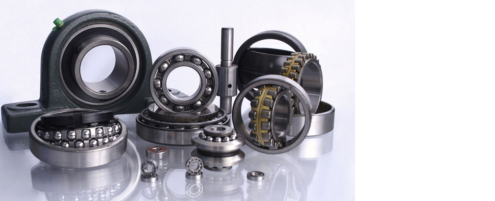
Wind turbines primarily use large spherical roller bearings in the main shaft, along with tapered roller bearings in the gearbox and deep groove ball bearings in the generator. Spherical roller bearings handle massive radial and axial loads while compensating for shaft misalignment caused by wind forces and tower flex.
Wind farms are demanding. They face unpredictable loads, constant vibration, and expensive downtime. The bearings inside are the unsung heroes. This article will explain the types used, why spherical rollers are so important, their limitations, and how turbine design impacts bearing life. This knowledge helps everyone from project engineers to parts distributors.
What type of bearings are used in wind turbines?
A single wind turbine is a complex machine. It uses different bearings in different places. Each location has a unique job. Getting the bearing type wrong in any spot can lead to a chain reaction of failures.
Main types include large spherical roller bearings1 for the main shaft, tapered roller bearings2 in the gearbox stages, and deep groove or cylindrical roller bearings3 in the generator and yaw/pitch systems. Each type is chosen for its specific load-handling capabilities in that part of the turbine.
The Bearing Ecosystem Inside a Turbine
Wind turbines are not simple machines. They combine massive structural support with high-speed precision. The bearing selection reflects this mix. Let’s walk through a turbine from the rotor to the generator.
The Main Shaft Bearing
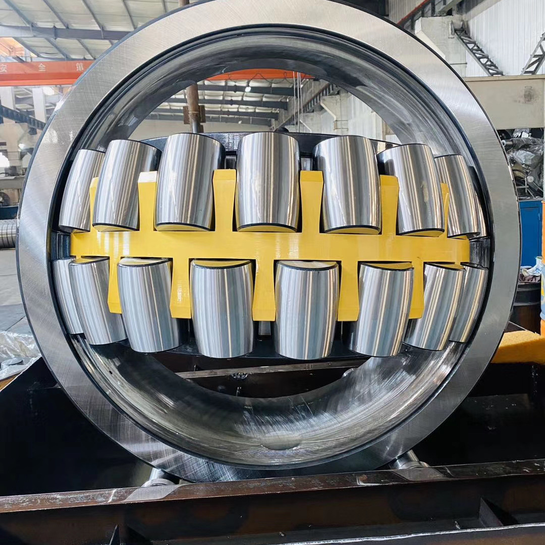
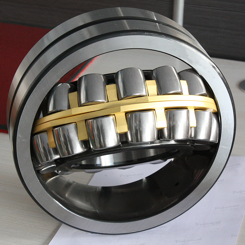
This is the king of turbine bearings. It sits just behind the rotor hub. Its job is to support the entire weight of the rotor and blades. It also handles powerful thrust loads from wind pressure and massive bending moments. For this brutal job, large bore spherical roller bearings are the standard choice. Their key advantage here is self-alignment. The tower flexes. The shaft deflects under load. A spherical roller bearing can tolerate this misalignment without creating damaging edge stresses. A rigid bearing like a cylindrical roller would likely fail quickly here.
The Gearbox Bearings
The gearbox increases the slow rotor speed to a high speed suitable for the generator. This creates complex loads. Gear meshing forces introduce heavy radial and axial loads. Tapered roller bearings are most common here. They excel at handling combined loads. They can be precisely adjusted during installation. This preload control is vital for gear alignment and smooth power transmission. Some designs also use cylindrical roller bearings3 for pure radial support on intermediate shafts.
The Generator Bearings
The generator runs at very high speeds (over 1000 RPM). The loads are primarily radial and relatively steady. Deep groove ball bearings are often used here. They are simple, reliable, and excellent for high-speed operation. For larger generators, cylindrical roller bearings3 might be used on the non-locating end to allow for shaft thermal expansion.
The Yaw and Pitch System Bearings
These systems turn the nacelle and adjust blade angles. They move slowly but under huge loads. Large diameter four-point contact ball bearings or crossed roller bearings4 are typical for yaw systems. They handle combined loads in a compact design. Pitch systems inside the hub often use smaller, heavy-duty deep groove ball bearings5 or angular contact ball bearings.
| Turbine Section | Primary Bearing Types | Why This Type is Used |
|---|---|---|
| Main Shaft | Spherical Roller Bearing (Large Bore) | Handles extreme radial & thrust loads; self-aligns to compensate for tower/shaft deflection. |
| Gearbox | Tapered Roller Bearings, Cylindrical Roller Bearings | Manages combined radial/axial gear forces; allows for precise preload adjustment. |
| Generator | Deep Groove Ball Bearings, Cylindrical Roller Bearings | Suitable for high-speed radial loads; simple and reliable. |
| Yaw System | Four-Point Contact Ball Bearings, Crossed Roller Bearings | Supports slow-rotation, heavy combined loads in a compact space. |
| Pitch System | Deep Groove Ball Bearings, Angular Contact Ball Bearings | Provides reliable rotation for blade adjustment under load inside the hub. |
The trend in newer turbines is toward direct-drive designs. These eliminate the gearbox. The main shaft connects directly to a large, low-speed generator. In these designs, the main bearing’s role is even more critical. It often remains a massive spherical roller bearing. The generator then uses a large array of bearings, sometimes special slewing bearings, to support the rotating assembly.
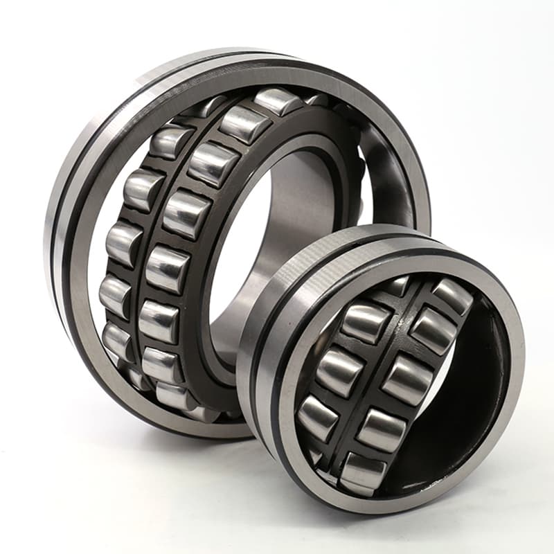
What are spherical roller bearings1 used for?
Many industries need bearings that can handle misalignment. We supply these bearings to many sectors, but their role in wind energy is particularly impressive. They solve a fundamental problem in large, flexible structures.
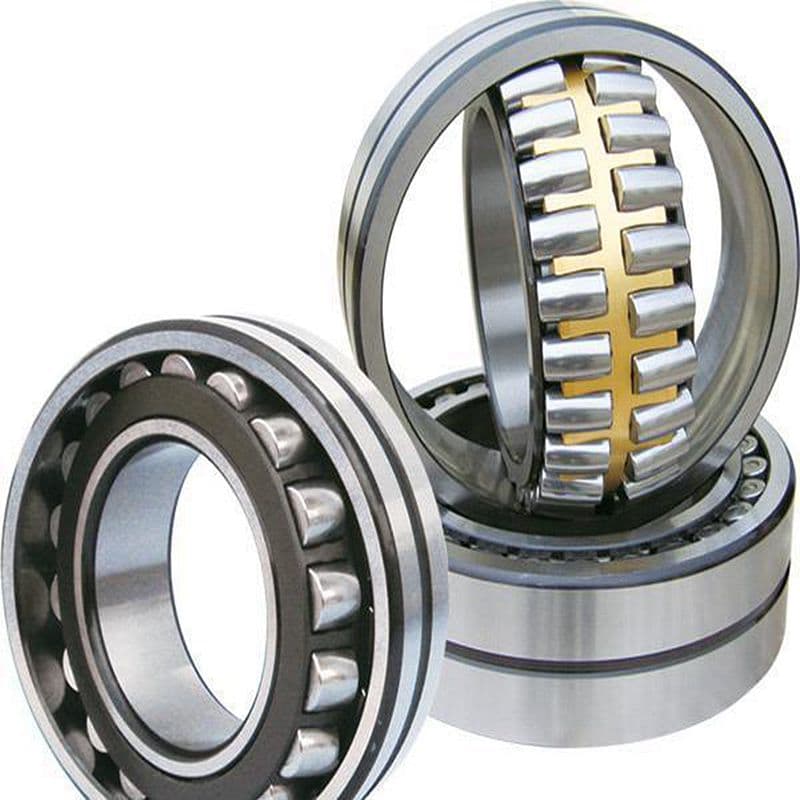
Spherical roller bearings are primarily used to support heavy radial loads2 combined with moderate axial loads in applications where shaft misalignment is expected. Their self-aligning capability3 makes them ideal for wind turbine main shafts4, industrial gearboxes5, mining conveyors6, paper mill rollers7, and ship propulsion systems8.
The Versatile Problem-Solver in Heavy Industry
The spherical roller bearing is a specialist. It is not a general-purpose bearing. Its design targets specific, tough problems found in capital-intensive industries. Its use is a deliberate engineering choice.
The Core Function: Managing Misalignment
All machinery has some misalignment. It comes from manufacturing tolerances, installation errors, or operational deflections. For a long shaft or a heavy housing, deflection under load is inevitable. A standard bearing cannot tilt inside its housing. If the shaft bends, the inner ring and outer ring of the bearing become misaligned. This forces the rolling elements to run at an angle. This causes high stress, uneven load distribution, heat, and rapid failure.
A spherical roller bearing solves this. Its outer ring has a spherical raceway. The rollers are barrel-shaped. This allows the entire inner ring and roller set to pivot inside the outer ring. The bearing can accommodate angular misalignment, typically up to 2-3 degrees. This keeps the load distributed evenly across the full length of the rollers. This dramatically increases bearing life in real-world, imperfect conditions.
Key Application Areas:
- Wind Energy: As the main shaft bearing, it handles bending from wind gusts and tower oscillation. This is its most high-profile modern application.
- Mining & Aggregates: Crushers, vibrating screens, and conveyor pulleys suffer from heavy shock loads and structural flexing. Spherical rollers are standard here.
- Pulp & Paper: Large dryer rolls expand with heat and sag under their own weight. Spherical roller bearings accommodate this movement, ensuring even paper tension.
- Marine & Offshore: Propulsion shafts on ships align poorly due to hull flex. Spherical roller bearings in the stern tube manage this.
- Steel Mills: Rolling mill stands experience enormous, fluctuating loads. Spherical rollers in the backup roll assemblies provide the necessary robustness and alignment tolerance.
- Industrial Gearboxes: Large, heavy gearboxes can warp slightly under load. Spherical roller bearings on the input or output shafts prevent internal binding.
| Industry | Typical Machine | Problem Solved by Spherical Roller Bearing |
|---|---|---|
| Renewable Energy | Wind Turbine Main Shaft | Compensates for tower flex and wind-induced shaft deflection. |
| Mining | Vibrating Screen, Crusher | Withstands extreme shock loads and frame distortion. |
| Marine | Ship Propulsion Shaft | Accommodates hull flex and misalignment in the stern tube. |
| Pulp & Paper | Dryer Drum | Allows for thermal expansion and roll sag under load. |
| Steel Production | Rolling Mill Stand | Handles colossal, unpredictable radial forces from metal deformation. |
For a bearing distributor, understanding these applications is key. When a customer in the mining sector needs a bearing for a vibrating screen, you don’t suggest a cylindrical roller bearing. You know the environment demands a spherical roller bearing with robust seals and high dynamic load capacity. Its ability to self-align is not just a feature; it is the core reason for its selection.
What are the disadvantages of spherical roller bearings?
Every engineering choice is a balance. Spherical roller bearings are powerful, but they are not magic. I have seen projects fail because designers only saw the advantages and ignored the limitations.
The main disadvantages of spherical roller bearings include higher rotational friction1 and lower maximum speed limits2 compared to ball bearings, greater sensitivity to improper installation preload3, higher cost due to complex manufacturing4, and a larger cross-sectional size5 for a given bore diameter.
Understanding the Limits to Make Better Choices
Spherical roller bearings excel in their niche. But using them outside that niche, or ignoring their requirements, leads to poor performance and short life. Let’s examine these disadvantages in detail.
Speed and Friction Limitations
The contact between a spherical roller and the raceway is a line contact. A ball bearing has point contact. Line contact supports heavier loads. But it also creates more rolling resistance (friction). More friction means more heat is generated inside the bearing. This heat must be dissipated. If the bearing rotates too fast, the heat generation can outpace the cooling. This causes the lubricant to overheat and break down. The bearing can then seize. Therefore, spherical roller bearings have a lower maximum permissible speed (dn value) than ball bearings of similar size. For a high-speed spindle or a turbocharger, a spherical roller bearing is the wrong choice.
Installation and Preload Sensitivity
While they tolerate operational misalignment, they can be sensitive to installation errors6. A common mistake is applying incorrect axial preload. Some spherical roller bearing designs (like the CC type with a floating guide ring) have very specific clearance requirements. Over-tightening the bearing axially during mounting can eliminate internal clearance. This leads to preload, excessive heat, and rapid fatigue. The installation must follow the manufacturer’s specifications precisely. This requires skilled technicians, which adds to the total cost of ownership.
Cost and Size Considerations
The internal geometry of a spherical roller bearing is complex. The spherical outer ring raceway and the barrel-shaped rollers are more difficult to grind with high precision than the straight races of a cylindrical bearing. This specialized manufacturing increases the unit cost. Furthermore, to achieve its high load capacity and self-alignment feature, the bearing has a larger cross-section. It is wider and has a larger outside diameter for a given bore size compared to a deep groove ball bearing. This demands more space in the housing, which can lead to larger, heavier, and more expensive machine designs.
Other Considerations
- Vibration and Noise: At very high precision levels, a spherical roller bearing may not run as quietly as a high-precision ball bearing due to more moving parts and guide rings.
- Lubrication Demand: The higher friction and heat generation mean proper lubrication is even more critical. They often require larger grease quantities or continuous oil circulation systems.
| Disadvantage | Cause | Consequence |
|---|---|---|
| Lower Speed Limit | High friction from line contact roller design. | Not suitable for very high-speed applications (e.g., machine tool spindles, small electric motors). |
| Higher Friction | Larger contact area between rollers and raceways. | Increased heat generation, higher energy loss, demands more robust lubrication/cooling. |
| Installation Sensitivity | Complex internal design with guide rings/centering lips. | Incorrect axial preload during mounting can cause immediate failure. Requires skilled labor. |
| Higher Cost | Complex geometry requiring precision grinding. | Higher initial purchase price per bearing unit. |
| Larger Cross-Section | Need to accommodate spherical raceway and roller set. | Requires larger, heavier housings, increasing overall machine size and material cost. |
For a wind turbine designer, these disadvantages are accepted trade-offs. The low speed of the main shaft is not a problem. The high load capacity and self-alignment are absolute necessities. The cost and size are justified by the critical role the bearing plays. The key is to use this bearing where its strengths are needed and its weaknesses don’t matter.
What is the best shape for a wind turbine rotor?
The rotor is the heart of the turbine. Its shape decides how much energy is captured and, crucially, what forces are transmitted to the drivetrain and bearings. It’s a question of aerodynamics and mechanical stress.
The best shape for a modern utility-scale wind turbine rotor is a three-bladed, horizontal-axis design with blades that are twisted and tapered. This shape provides the optimal balance of high efficiency, structural stability, smooth power output, and acceptable loads on the tower and bearings.
The Aerodynamic and Mechanical Logic Behind the Design
The classic three-blade design did not win by accident. It is the result of decades of optimization balancing energy capture, cost, durability, and load management. Every aspect of this shape impacts the bearings downstream.
Why Three Blades?
It’s a compromise. One blade would be unbalanced, causing huge vibration. Two blades are better but still have significant gyroscopic forces and visual "chopping" effects. Three blades create a rotor that is nearly symmetrical at any point in its rotation. This symmetry leads to:
- Smooth Power Output: The torque delivered to the main shaft has fewer pulsations. This reduces cyclic loading on the gearbox and bearings.
- Reduced Vibration: The rotor’s center of mass stays closer to the center of rotation. This minimizes dynamic imbalance and shaking forces transferred to the nacelle and tower.
- Aesthetic Acceptance: The three-blade rotor turns at a visually pleasing, slower-looking speed, which is important for public acceptance.
Why Horizontal-Axis (HAWT)?
Vertical-axis wind turbines (VAWTs) exist. But for large-scale power generation, Horizontal-Axis Wind Turbines (HAWTs) dominate. The main reason is efficiency. HAWT blades operate at a constant, optimal angle of attack as they rotate. They can also be pitched to control power in high winds. VAWTs have parts of the blade that stall and create drag, lowering overall efficiency. For HAWTs, the main bearing and shaft are in a horizontal position, which is a more straightforward and robust mechanical arrangement for handling the primary loads.
Blade Geometry: Twisted and Tapered
A blade is not a simple plank. It is an aerodynamic wing. The wind speed experienced by the blade is faster at the tip than at the root (because the tip travels a longer distance in the same time). To extract energy efficiently along the entire blade length, the angle of attack must be optimized for each section. This is achieved by twisting the blade. The blade also tapers (gets thinner) from root to tip. This reduces material, weight, and cost. More importantly, it balances the bending loads. The root experiences the highest bending moment, so it is thick and strong. The tip can be slender and fast.
| Rotor Characteristic | Best Practice Design | Reason & Impact on Drivetrain/Bearings |
|---|---|---|
| Number of Blades | Three | Provides smooth torque & minimal vibration, reducing cyclic fatigue on main bearings and gearbox. |
| Axis Orientation | Horizontal (HAWT) | Enables higher aerodynamic efficiency and simpler, more robust main shaft and bearing support. |
| Blade Profile | Twisted & Tapered Airfoil | Optimizes energy capture along blade length; reduces blade weight and root bending loads transferred to the hub and main shaft. |
| Rotation Speed | Variable (Modern) | Allows optimization for different wind speeds; reduces extreme load spikes on the drivetrain during gusts. |
| Control Mechanism | Full Span Pitch Control | Each blade can rotate to feather in storms, drastically reducing thrust load on the main bearing in survival conditions. |
The bearing engineer cares deeply about this shape. A three-bladed rotor means smoother, more predictable loads on the main spherical roller bearing. The horizontal axis means the bearing primarily sees radial loads from rotor weight and wind thrust, with some axial component—a perfect scenario for a spherical roller. Advanced pitch control allows the loads to be managed actively, protecting the bearing during extreme events. The "best" rotor shape is ultimately the one that delivers reliable, low-cost energy while imposing the most manageable mechanical loads on the components we build and supply.
Conclusion
For wind turbines, spherical roller bearings are essential for the main shaft. Their self-alignment handles real-world flex, but designers must respect their speed and friction limits. The optimal three-blade rotor design exists in harmony with these robust bearings.
-
Understanding the impact of friction can help in selecting the right bearing for your application. ↩ ↩ ↩
-
This information is crucial for applications requiring high-speed performance. ↩ ↩ ↩
-
Learn about the importance of correct installation to avoid costly failures. ↩ ↩ ↩ ↩ ↩
-
Understanding manufacturing costs can help in budgeting for projects. ↩ ↩ ↩
-
This knowledge is essential for designing compact machinery. ↩ ↩ ↩
-
Identifying potential mistakes can help ensure successful bearing installation. ↩ ↩
-
Learn about the unique challenges in paper production and how these bearings ensure consistent tension and performance. ↩
-
Discover how these bearings accommodate hull flex and misalignment, ensuring smooth operation in marine environments. ↩