
A bearing doesn’t fail because of its age. It fails because stress concentrates on a single weak point. In spherical roller bearings, how the load spreads across each roller decides its lifespan. Poor distribution cuts life by 90% or more. Understanding this is the key to reliability.
Optimal load distribution across all rollers in a spherical roller bearing maximizes service life by preventing localized overstress. Factors like proper alignment, correct internal clearance, and avoiding excessive preload are critical to achieving even load sharing and realizing the bearing’s full calculated life potential.
The promise of a long service life is based on perfect load sharing. In reality, installation errors, operational stresses, and design limitations disrupt this ideal. To protect your bearing’s life, we must explore what loads it can handle, its inherent weaknesses, how setup affects load sharing, and why its design is still unbeatable for heavy loads.
What loads can a spherical roller bearing handle?
Spherical roller bearings are known for their strength, but their capabilities have specific boundaries. Assuming they can handle any load in any direction is a mistake that leads to quick, expensive failures. You must match the load profile to the bearing’s design strengths.
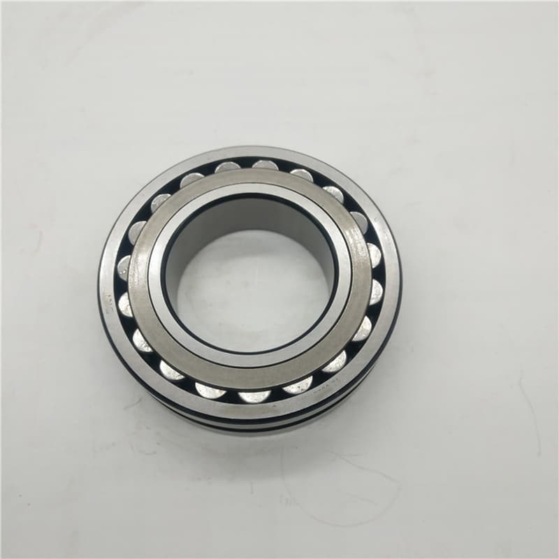
Spherical roller bearings are designed to handle very heavy radial loads1 and moderate axial (thrust) loads in both directions. They excel at managing combined loads (radial + axial) simultaneously, especially in applications with unavoidable shaft misalignment, where their self-aligning feature ensures proper load distribution.
Mapping the Load-Bearing Landscape
The bearing’s internal geometry2—the curved raceways and barrel-shaped rollers—defines its load-handling profile. Let’s break down how it manages different force types.
1. Radial Loads (The Primary Strength)
This is the force pressing perpendicular to the shaft, like the weight on a conveyor pulley.
- Capacity: Spherical rollers have an extremely high radial load capacity. This is due to the line contact between the barrel-shaped rollers and the raceways. The contact area is large, which spreads the force over a bigger surface, reducing stress. For the same outer dimensions, a spherical roller bearing often has a higher radial load rating than other types.
- Distribution: Under pure radial load, ideally, all rollers in the load zone share the force equally. The lower half of the bearing carries the load.
2. Axial (Thrust) Loads
This is the force pushing along the shaft axis.
- Capacity: They can handle moderate axial loads3 in both directions. This is because of their symmetrical internal design and the two rows of rollers. One row will engage to handle thrust in one direction, the other row for the opposite direction.
- Mechanism: When axial load is applied, it is transferred through the roller ends to the guiding flanges on the inner ring. The capacity is limited by the strength of these flanges and the roller ends.
3. Combined Loads (The Real-World Scenario)
This is where they are most valuable. In reality, radial and axial loads often occur together.
- Example: A gearbox shaft has radial load from the gear teeth and axial load from helical gears. The bearing resolves these forces. The load is distributed between the two rows of rollers based on the angle of the applied force.
4. Moment Loads (Tilting Forces)
They have good resistance to moment loads4—forces that try to tilt the inner ring relative to the outer ring. This is due to the wide spacing between the two rows of rollers, which creates a stable "footprint."
| Load Type | Spherical Roller Bearing Capability | Limiting Factor | Comparison to Other Bearings |
|---|---|---|---|
| Pure Radial Load | Excellent (Very High Capacity) | Material fatigue strength of rollers/raceways. | Higher than same-size ball bearing; comparable to cylindrical roller bearing. |
| Pure Axial Load | Good (Moderate Capacity, Both Directions) | Strength of roller ends and guide flanges. | Lower than dedicated thrust ball bearing; good for a radial bearing type. |
| Combined Radial + Axial | Excellent | Complex stress in rollers and raceways. | Better than cylindrical roller (handles no thrust); different trade-off vs. tapered roller. |
| Moment (Tilting) Load | Good | Spacing between the two roller rows. | Good due to wide footprint. |
For an application like a heavy mining conveyor, the bearing faces massive radial load from the belt tension and weight, plus some axial load from misalignment. The spherical roller bearing’s ability to handle this combined load profile while also self-aligning is why it’s the chosen solution. However, if the axial load is extremely high (like in a large vertical pump), a dedicated thrust bearing paired with a radial bearing might be a better system.
What are the disadvantages of spherical roller bearings?
Every engineering choice is a trade-off. The spherical roller bearing’s great strengths come with specific compromises. Ignoring these disadvantages during selection or operation directly sabotages load distribution and kills service life prematurely.
Key disadvantages include higher friction and operating temperature1 than ball bearings, sensitivity to lubrication quality and quantity, lower maximum speed limits2, and more complex/expensive construction. These factors, if not managed, lead to uneven load distribution, localized overheating, and accelerated fatigue.
How Weaknesses Directly Attack Load Distribution and Life
Let’s connect each disadvantage to the concrete problem of poor load sharing. This is not theoretical; it’s what we see in failed bearings returned for analysis.
1. Friction, Heat, and Thermal Distortion
- The Problem: The line contact and sliding at the roller-guide flange interface generate significant friction. Friction creates heat.
- Impact on Load Distribution: Heat is not uniform. The hottest part of the inner ring (usually under the load zone) expands more than the cooler parts. This thermal distortion3 changes the bearing’s internal geometry. The raceway groove shape can warp slightly. This distortion prevents rollers from making even contact. Some rollers take more load, others take less. The overloaded rollers fatigue much faster.
- Mitigation: Use correct internal clearance (C3/C4) to accommodate thermal expansion. Ensure effective lubrication to reduce friction. Consider cooling for very heavy-duty applications.
2. Lubrication Sensitivity
- The Problem: The complex internal space with two roller rows and a center flange is challenging to lubricate effectively. If the lubricant film breaks down, metal-to-metal contact begins.
- Impact on Load Distribution: Without a proper lubricant film, friction skyrockets locally. This causes scuffing or smearing on the roller ends or guide flanges. This surface damage creates high points and rough spots. These imperfections act as stress concentrators. They also physically prevent smooth roller movement, disrupting the even sharing of load across the roller set.
- Mitigation: Select a high-quality, extreme-pressure (EP) grease4 with good adhesive properties. Follow strict relubrication intervals. Ensure the bearing is filled with the correct amount of grease (not too little, not too much).
3. Speed Limitations
- The Problem: High centrifugal force at very high speeds can cause rollers to skid or distort the cage. The friction-related heat also builds faster.
- Impact: At excessive speeds, the bearing cannot maintain proper kinematic motion. Rollers may not roll correctly, leading to sliding and uneven wear. This disturbs load distribution.
- Mitigation: Respect the catalog’s speed ratings. For high-speed needs, consider angular contact ball bearings or cylindrical roller bearings.
4. Cost and Complexity
- The Problem: They are more expensive than deep groove ball bearings.
- Impact: This sometimes tempts users to select a smaller or lower-quality bearing to save money. An under-sized bearing is immediately overloaded. A low-quality bearing may have poor geometric accuracy from the start, meaning load is never evenly distributed, even when new.
| Disadvantage | Primary Cause | Direct Effect on Load Distribution | Result on Service Life |
|---|---|---|---|
| High Friction & Heat | Line contact, sliding | Thermal distortion of raceways, uneven roller contact. | Dramatic reduction due to localized overstress and material softening. |
| Lubrication Sensitivity | Complex geometry | Film breakdown leads to surface damage, creating high spots. | Accelerated surface fatigue (spalling) starting at damage points. |
| Lower Speed Limit | Centrifugal forces, heat | Roller skidding, improper kinematic motion. | Increased wear, unpredictable failure mode. |
| Higher Cost | More parts, complex machining | May lead to selection of undersized/poor-quality bearings. | Catastrophic reduction if bearing is under-capacity. |
Understanding these links is crucial. For instance, a bearing in a hot, slow-moving kiln might fail not from load, but from thermal distortion3 caused by its own friction because the wrong clearance (C3 instead of C4) was used. The load didn’t break it; the uneven load distribution caused by heat did.
How to preload a roller bearing?
Preload is a deliberate axial force applied to a bearing to eliminate internal clearance. For spherical roller bearings1, the topic of preload is critical and often misunderstood. Incorrect preload is a major destroyer of optimal load distribution and service life.
Spherical roller bearings are generally NOT preloaded in the traditional sense like machine tool spindle bearings. Instead, they are set with a specific axial "endplay" or slight clearance. Attempting to preload a spherical roller bearing typically causes excessive heat, high friction, and drastically reduced life due to overload of all rollers.
Setting Spherical Roller Bearings: Clearance, Not Preload
The goal with spherical rollers is to achieve a controlled internal state that allows for thermal expansion and ensures no roller is unloaded or excessively loaded during operation. This is done through careful axial positioning.
Why Preload is Usually Wrong for Spherical Rollers:
- Design Purpose: Spherical roller bearings are designed for misalignment accommodation and high load capacity2. Preload works against both. Preload removes internal freedom, reducing the ability to self-align. It also puts all rollers under constant stress, even with no external load, which increases friction and heat.
- The Result of Preload: If you axially clamp a pair of spherical rollers to zero clearance, you force the rollers hard against the guide flanges. The bearing will run very hot, the grease will degrade quickly, and the bearing will likely fail from thermal seizure or fatigue in a short time.
The Correct Method: Setting Axial Endplay
In most industrial applications, spherical roller bearings1 are mounted in a "locating" and "non-locating" arrangement.
- Locating Bearing: This bearing is fixed axially on the shaft and in the housing. It handles axial loads in both directions.
- Non-Locating Bearing: This bearing has freedom to move axially in its housing. It allows for shaft thermal expansion3.
- The "Locating" Bearing Setting: Even the locating bearing is not preloaded. It is set with a small amount of axial endplay4 (shuttle). This is typically between 0.1mm and 0.5mm, depending on bearing size. This endplay ensures that under operating temperature, the bearing does not become preloaded by thermal expansion3.
How to Set the Axial Endplay:
- Mount the bearings and related components (shaft, housing, seals).
- Tighten the axial locking device (like a locknut) to a specified torque to seat the components.
- Use a dial indicator to measure the axial movement of the shaft relative to the housing.
- Adjust shims or the locknut position until the measured axial endplay4 matches the manufacturer’s recommendation for that specific bearing and application.
- Secure the adjustment with a lock washer or second nut.
Exceptions: When a "Preloaded" Feel is Needed
In some applications with very high vibration (like vibrating screens), a slight axial pinch5 might be applied during mounting. This is not true preload for rigidity. It is to prevent the bearing from "walking" axially in its housing due to vibration. Even here, the goal is to eliminate excessive free axial movement, not to create internal preload stress.
| Bearing Type | Typical Mounting Goal | Purpose | Consequence of Error |
|---|---|---|---|
| Spherical Roller Bearing | Controlled Axial Endplay (Clearance) | Allow for thermal expansion3, prevent operational preload. | Too tight: Overheating, rapid failure. Too loose: Excessive axial movement, impact loads. |
| Tapered Roller Bearing Pair | Controlled Preload or Clearance | Provide system rigidity, precise shaft positioning. | Incorrect setting leads to noise, heat, or lack of stiffness. |
| Angular Contact Ball Bearing (Pair) | Preload | Maximize rigidity for high-speed, high-precision spindles. | Incorrect preload affects accuracy, speed, and life. |
For a maintenance team installing a new spherical roller bearing in a gearbox, following the manual’s endplay specification is vital. Guessing or "tightening it up good" will distort load distribution from day one. The bearing will never reach its potential life because the installers unintentionally preloaded it.
What makes spherical roller systems ideal for heavy duty applications?
Heavy-duty means more than big loads. It means shock, dirt, misalignment, and constant punishment. A single bearing feature isn’t enough; it’s the system of features in a spherical roller bearing1 that creates its legendary durability in these conditions. This systemic strength is what enables reliable load distribution2 under the worst circumstances.
Spherical roller bearing systems are ideal for heavy-duty applications due to three integrated features: self-alignment that compensates for mounting errors and shaft deflection, high load capacity from two rows of barrel rollers, and robust construction that withstands shock and contamination. This combination ensures load is distributed effectively even in imperfect, harsh environments.

The Synergy of Features in a Hostile World
Let’s examine how each feature of the system works together to protect load distribution2 and service life where other bearings would fail quickly.
1. Self-Alignment: The Foundation of Even Load Sharing
This is the most critical feature for heavy-duty applications3.
- The Problem: In heavy machinery, perfect alignment between the shaft and housing is impossible. Foundations settle. Shafts bend under load. Housings get knocked.
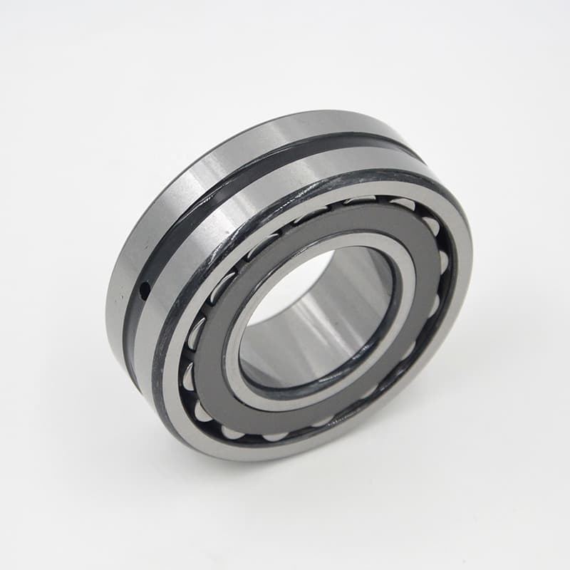
- The Spherical Solution: The outer ring has a spherical raceway. The inner ring with rollers and cage can pivot inside it (typically ±2-3°). This means the rolling assembly always aligns itself with the shaft.
- Load Distribution Impact: Because the inner ring aligns with the shaft, the rollers maintain full line contact with the raceways along their entire length. If the bearing could not align, the rollers would contact only on their edges. This edge loading creates huge localized stress, spalling, and rapid failure. Self-alignment ensures the load is spread over the maximum possible contact area.
2. High Load Capacity: The Strength to Carry the Weight
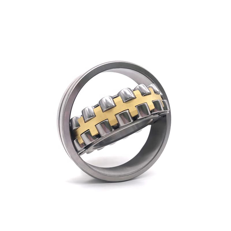
- Two Rows of Rollers: Doubles the number of load-carrying elements compared to a single-row bearing.
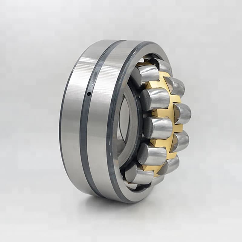
- Barrel-Shaped Rollers: The curved profile of the rollers matches the curved raceways. This geometry minimizes edge stresses, even under misalignment, and allows the bearing to handle combined radial and axial loads effectively.
- Robust Cage: Heavy-duty cages (pressed steel or machined brass) keep the rollers precisely spaced, preventing them from colliding and ensuring smooth load transfer from one roller to the next as the bearing rotates.
3. Durability Against Environmental Assaults
- Sealing Options: Many spherical roller bearing1s come with integral seals (e.g., 2RS) or are used in sealed housing units4. This keeps abrasive dirt and moisture out, preserving the lubricant and smooth raceway surfaces essential for even load distribution2.
- Internal Design: Modern designs often have improved roller profiles and surface finishes that reduce internal stress concentrations, making the bearing more tolerant of occasional overloads or shock loads.
The System in Action: A Conveyor Drive Pulley
Imagine the head pulley of a mining conveyor. It has huge radial load from the belt tension. The shaft deflects. The environment is dusty.
- A cylindrical roller bearing would handle the radial load but fail from misalignment.
- A deep groove ball bearing would have insufficient capacity.
- The spherical roller bearing1 system works: It self-aligns with the deflected shaft, its two rows of rollers carry the heavy load, and a sealed housing unit keeps out dirt. This systemic approach maintains proper load distribution2 for tens of thousands of hours.
| Heavy-Duty Challenge | Spherical Roller Bearing System Response | Benefit for Load Distribution |
|---|---|---|
| Shaft Deflection / Misalignment | Self-aligning inner ring/roller assembly. | Maintains full roller-raceway contact, prevents edge loading. |
| Extreme Radial Loads | Two rows of barrel rollers with large contact area. | Shares load across many rollers, reducing stress per roller. |
| Shock and Impact Loads | Robust construction, ductile steel, optimized profiles. | Absorbs energy without permanent deformation that would disrupt geometry. |
| Contaminated Environment | Available with integral seals or in sealed housings. | Protects raceway and roller surfaces from abrasives that cause stress risers. |
For engineers and buyers like Rajesh’s clients, this systems view explains why spherical roller bearing1s are the default choice for mining, cement, steel, and pulp & paper machinery. They aren’t just strong; they are forgiving and resilient. They are designed as a system to maintain the holy grail of even load distribution2 in a world that constantly tries to disrupt it. This systemic reliability is what delivers the long service life promised in the catalog.
Conclusion
The service life of a spherical roller bearing is a direct function of load distribution. Achieve even sharing through correct application, management of the bearing’s disadvantages, proper installation without preload, and leveraging its systemic strengths for harsh, heavy-duty environments.
-
Explore the advantages of spherical roller bearings, especially in harsh environments, to understand their unique benefits. ↩ ↩ ↩ ↩ ↩ ↩ ↩ ↩
-
Find out how spherical roller bearings ensure even load distribution, enhancing their performance in heavy-duty applications. ↩ ↩ ↩ ↩ ↩ ↩ ↩ ↩
-
Explore the various industries that rely on heavy-duty spherical roller bearings for their machinery and equipment. ↩ ↩ ↩ ↩ ↩ ↩ ↩
-
Learn about the advantages of sealed housing units in protecting bearings from contaminants and extending their life. ↩ ↩ ↩ ↩ ↩
-
Learning about axial pinch can help in preventing bearing movement in high-vibration applications. ↩