
Heavy loads and shock forces in industrial machines demand more than just a strong bearing; they demand precise control over shaft movement. A standard bearing under such conditions can allow excessive play, leading to vibration, gear misalignment, and premature failure of connected components.
High load tapered roller bearings excel at handling combined radial and axial forces, particularly in one direction. Their design allows them to be precisely adjusted (preloaded) to eliminate internal clearance, providing maximum rigidity, accurate shaft positioning, and extended life in demanding applications like gearboxes, rolling mills, and heavy vehicle axles.
The term "high load" is common, but the science behind it is specific. Tapered roller bearings are not just strong; they are controllable. Their performance hinges on correct load calculation and precise installation. Misunderstanding these points leads to bearing failure and machine damage. Let’s examine the core principles that make them indispensable.
What loads can a tapered roller bearing1 handle?
Many bearings fail because they are asked to handle forces they were not designed for. A bearing that can only handle radial load will be destroyed if significant axial thrust2 is applied. This mismatch is a frequent cause of failure in power transmission systems.
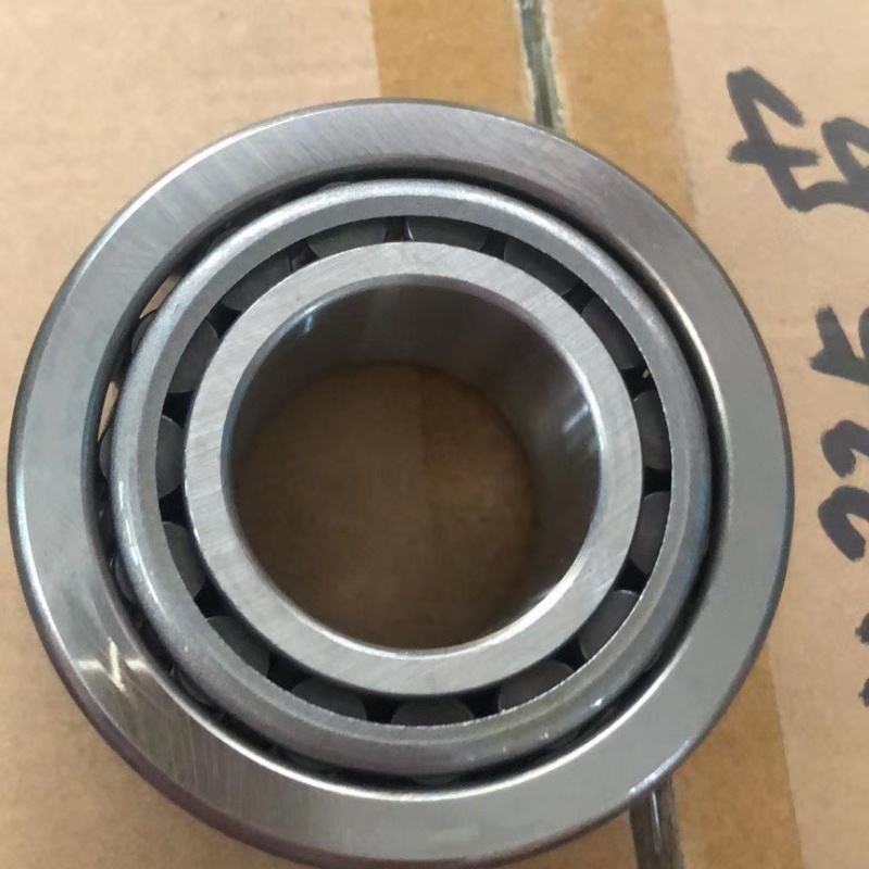
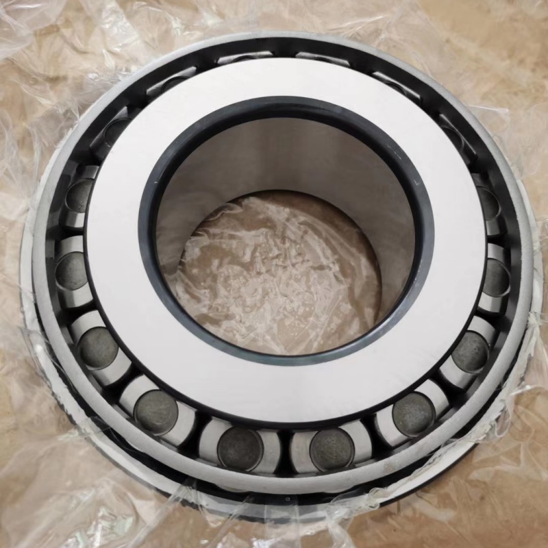
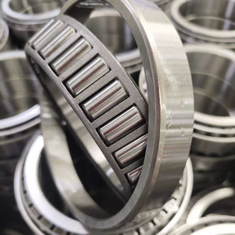
A tapered roller bearing1 is uniquely designed to handle combined loads3—both heavy radial loads and significant axial (thrust) loads, primarily in one direction. The load capacity4 is very high due to the line contact of the tapered rollers. They are not typically used for pure axial loads or for axial loads reversing direction without a second, opposing bearing.

The Geometry of Combined Load Capacity
The ability to handle combined loads3 is not an accident; it is a direct result of the bearing’s geometry. Unlike a deep groove ball bearing that handles axial load as a secondary feature, the tapered roller bearing1 is optimized for it. To understand its capabilities, we must look at the angles and forces inside.
The bearing’s components are conical. The inner ring (cone), outer ring (cup), and rollers all have tapered surfaces. This geometry means any radial load applied to the bearing generates an induced axial (thrust) load component. This is due to the angle of contact. Think of a wedge being driven in; a downward force (radial) creates an outward force (axial).
This characteristic dictates two important rules for their use:
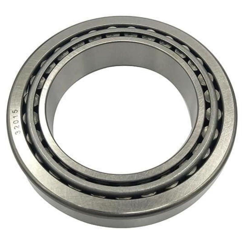
- They must be used in pairs, facing opposite directions. One bearing handles axial thrust2 in one direction, and its paired partner handles thrust in the opposite direction. This stabilizes the shaft axially.
- They are excellent for applications with fixed direction axial loads, such as gear shafts (where helical gears create thrust) or vehicle wheel hubs (where cornering forces create thrust).
Let’s compare the load-handling profile of tapered roller bearing1s to other common types in high-load scenarios:
| Bearing Type | Radial Load Capacity | Axial Load Capacity | Key Limitation for Combined Loads |
|---|---|---|---|
| Tapered Roller Bearing | Very High | Very High (One Direction) | Requires precise adjustment (preload/clearance5). Sensitive to misalignment. |
| Spherical Roller Bearing | Very High | Good (Both Directions) | Lower axial capacity than tapered rollers for same size. Higher friction. |
| Cylindrical Roller Bearing | Highest (Pure Radial) | Very Low | Cannot handle axial thrust2. |
| Deep Groove Ball Bearing | Moderate | Moderate (Both Directions) | Load capacity is limited by point contact. |
The key takeaway is that tapered roller bearing1s offer the best combination of high radial and high one-direction axial capacity. For a gearbox designer in Brazil working on a heavy-duty transmission, this is critical. Helical gears generate constant axial thrust2. Using a pair of preloaded tapered roller bearing1s locks the gear shaft in perfect axial position, ensuring quiet, efficient gear mesh and long life. At FYTZ, when we supply these bearings to OEMs, we often provide them in matched sets for such critical applications, ensuring consistency in performance.
What is the load capacity of roller bearings?
Load capacity is the most important number on a bearing’s specification sheet, but it’s often misunderstood. There are two distinct ratings: one for when the bearing is spinning (dynamic), and one for when it is stationary or experiences shock (static). Confusing them leads to under-sizing or over-sizing.
The load capacity of a roller bearing is defined by two key ratings: the Dynamic Load Rating (C)1 and the Static Load Rating (C0)2. ‘C’ is the constant load a bearing can withstand for 1 million revolutions with a 90% survival rate. ‘C0’ is the maximum stationary load it can handle without permanent deformation3. These values are determined by the bearing’s size, material, and internal geometry.
Demystifying C and C0: The Two Pillars of Bearing Strength
The terms "dynamic" and "static" load rating are standardized (ISO 281 & ISO 76) but are frequently misapplied. They serve different purposes in the design and selection process. For tapered roller bearings used in industrial machinery, both are critically important.
1. Dynamic Load Rating (C)1: The Life Predictor
- Purpose: This rating is used to calculate the expected fatigue life (L10 life)4 of a bearing under a given operating load. Fatigue is the primary failure mode for bearings that rotate under load.
- Definition: It is the constant radial load (for radial bearings) that a group of identical bearings can endure for 1 million revolutions with a 90% probability of survival.
- Key Point: The life calculation is not linear. The basic formula for roller bearings is L10 = (C / P)^(10/3). This shows a powerful relationship: if the actual load (P) is doubled, the bearing’s theoretical life is reduced to about 1/10th. This underscores why selecting a bearing with a sufficiently high ‘C’ rating is vital for longevity.
2. Static Load Rating (C0)2: The Strength Limit
- Purpose: This rating ensures the bearing is not damaged by heavy stationary loads or severe shock loads that cause plastic deformation (brinelling) of the raceways.
- Definition: It is the static load which produces a calculated contact stress of 4000 MPa at the center of the most heavily loaded rolling element. In simpler terms, it’s the load limit before permanent dents appear.
- Key Point: This is critical for applications like crane hooks, lifting jacks, or any machinery that experiences high impact loads5 when starting or stopping. The applied static load (including shock factors) must always be less than C0.
For tapered roller bearings, these ratings are exceptionally high due to their line contact design. Here is a simplified comparison for similar bore sizes:
| Bearing Type (Example: 320mm Bore approx.) | Approx. Dynamic Load Rating (C)1 | Approx. Static Load Rating (C0)2 | Primary Design Focus |
|---|---|---|---|
| Tapered Roller Bearing | ~1,200 kN | ~2,000 kN | Combined high radial & axial load. |
| Spherical Roller Bearing | ~1,400 kN | ~2,800 kN | Very high radial load with self-alignment. |
| Cylindrical Roller Bearing | ~1,600 kN | ~3,000 kN | Highest pure radial load. |
When a client from the mining sector in South Africa needs bearings for a dragline hoist, they focus heavily on the static load rating (C0) because of the immense shock loads. For a continuous running conveyor gearbox in a cement plant in Vietnam, the dynamic load rating (C) and life calculation are more important. At our factory, we test our bearings to verify these ratings. This data gives our distributors, like Rajesh in India, the confidence to recommend FYTZ tapered roller bearings for demanding applications, knowing they meet international performance standards.
How to calculate bearing load capacity1?
A common mistake is to simply divide the total machine weight by the number of bearings. This ignores force multipliers like gear meshes, belt tensions, and dynamic shock loads. An under-calculated load leads to rapid bearing fatigue2 and unexpected downtime.
You calculate the required bearing load capacity1 by first determining the equivalent dynamic load (P)3 acting on the bearing. For tapered roller bearings, this combines the actual radial (Fr) and axial (Fa) loads using the bearing’s specific factors (e, Y). You then use this ‘P’ value and the bearing’s catalog ‘C’ rating in the life formula L10 = (C/P)^(10/3) to select a bearing with adequate capacity and life.
From Machine Forces to Bearing Selection: A Step-by-Step Methodology
The calculation process bridges the gap between the complex forces in a machine and the simple catalog number of a bearing. It’s a systematic approach that ensures reliability. For tapered roller bearings, this process is detailed due to their interaction with combined loads.
Step 1: Determine the Actual Applied Loads (Fr and Fa)
This is the most difficult step and often requires mechanical analysis or measurement.
- Radial Load (Fr): Forces perpendicular to the shaft (e.g., gear tooth forces, belt tension, pulley weight).
- Axial Load (Fa): Forces parallel to the shaft (e.g., thrust from helical gears, fluid pressure in pumps).
Step 2: Calculate the Equivalent Dynamic Load (P)
Because loads are combined, we convert them into a single hypothetical radial load that would cause the same fatigue damage. The formula is:
P = X Fr + Y Fa
Where:
- X is a radial load factor.
- Y is an axial load factor.
- The values of X and Y depend on the ratio Fa/Fr and a constant factor ‘e’ unique to each bearing, found in manufacturer catalogs.
Step 3: Factor in Application Conditions
The basic life formula assumes ideal conditions. Real-world conditions are accounted for with adjustment factors (a1, aISO).
- Reliability Factor (a1): The L10 life4 is for 90% reliability. For higher reliability (e.g., 95%, 99%), a lower a1 factor is used.
- Operating Condition Factor (aISO): This considers lubrication, contamination levels, and temperature. Poor conditions drastically reduce life.
Step 4: Perform the Life Calculation and Select Bearing
The adjusted life formula is: L10h = (a1 aISO) (1,000,000/(60n)) (C/P)^(10/3)
- L10h is the life in operating hours.
- ‘n’ is the speed in RPM.
- ‘C’ is the dynamic load rating from the catalog.
You select a bearing whose ‘C’ rating gives you the desired L10h life for your calculated ‘P’.
Consider this simplified example for a gear shaft:
| Parameter | Value | Notes |
|---|---|---|
| Radial Load (Fr) | 15,000 N | From gear tooth pressure. |
| Axial Load (Fa) | 5,000 N | From helical gear angle. |
| Speed (n) | 500 rpm | Shaft rotational speed. |
| Target Life | 30,000 hours | Design requirement. |
| Condition Factor (aISO) | 0.8 | Good lubrication, some contamination. |
| From Catalog for a bearing: | ||
| Dynamic Load Rating (C) | 120,000 N | Candidate bearing. |
| Factors e, Y | e=0.4, Y=1.5 | From catalog for Fa/ Fr ratio. |
| Equivalent Load (P) | = 0.415,000 + 1.55,000 = 13,500 N | Calculated. |
| Calculated L10h | = 0.8 (1e6/(60500)) * (120,000/13,500)^(10/3) ≈ 45,000 hrs | Exceeds 30,000 hrs target. Bearing is suitable. |
For our OEM clients, we provide technical support for these calculations. When a gearbox manufacturer in Turkey sends us their load data, we can suggest the optimal FYTZ tapered roller bearing size and arrangement. This service adds immense value beyond just selling a component. It ensures their final product is reliable.
How to preload a taper roller bearing?
Incorrect preload is the number one cause of premature tapered roller bearing failure. Too little preload (clearance) allows shaft movement, causing vibration and noise. Too much preload creates excessive friction and heat, leading to lubrication breakdown and rapid wear.
Preloading a tapered roller bearing means applying a controlled axial force to eliminate all internal clearance, creating a slight compressive stress. Common methods include using spacer sleeves between bearing cups with a defined clamping force1, adjusting a threaded nut with a dial indicator to measure starting torque, or using crush sleeves (in automotive) or Belleville washers2 to maintain a set preload.
The Art and Science of Achieving Optimal Rigidity
Preload is not a "set and forget" guess. It is a precise setting that balances rigidity against friction and heat generation. The goal is to achieve zero operational clearance under load, ensuring perfect shaft positioning without overheating the bearing.
Why Preload is Necessary:
Tapered roller bearings have inherent internal clearance when mounted normally. Under load, this clearance allows the shaft to deflect slightly. For precision applications like machine tool spindles or high-performance gearboxes3, this deflection is unacceptable. Preload removes this clearance, making the bearing assembly extremely rigid.
Methods of Preloading:
-
Fixed Position Preload (Rigid Spacers)4:
- How it works: Precision-ground spacer rings are installed between the outer rings (cups) and/or inner rings (cones). When the housing end cap or shaft nut is tightened, the bearings are forced together axially to a fixed position determined by the spacer length.
- Advantage: Maintains a constant, precise preload. Excellent for high rigidity.
- Disadvantage: Requires very precise machining of spacers and housing. Does not compensate for thermal expansion.
-
Constant Pressure Preload (Springs)5:
- How it works: A spring (like a Belleville washer stack) applies a constant axial force to the bearing outer ring, maintaining preload regardless of thermal expansion or minor wear.
- Advantage: Compensates for thermal changes, maintaining consistent preload.
- Disadvantage: The preload force is generally lower, providing less ultimate rigidity than fixed position.
-
Adjustment Preload (Threaded Nut)6:
- How it works: This is the most common method for field adjustment. A lock nut on the shaft is tightened while measuring either:
- Axial Play: Using a dial indicator to reduce axial shaft movement to zero, then adding a defined turn (e.g., 1/16 of a turn).
- Starting Torque: Using a torque wrench to turn the nut until a specific rotational torque is felt when spinning the shaft.
- Procedure Example (Simplified):
- Hand-tighten the nut to seat the bearings.
- Back off the nut slightly so the bearing has slight clearance.
- Attach a dial indicator to measure axial shaft play.
- Gradually tighten the nut while rocking the shaft, until all axial play is eliminated (dial indicator reads zero movement).
- Further tighten the nut by a specified amount (from the bearing manufacturer’s manual, often related to thread pitch) to apply the correct preload. For example, for a fine-pitch nut, 1/16 of a turn past zero clearance.
- Secure the lock nut or use a tab washer.
- How it works: This is the most common method for field adjustment. A lock nut on the shaft is tightened while measuring either:
The Consequences of Incorrect Preload:
| Preload Condition | Symptoms | Result |
|---|---|---|
| Excessive Preload | High operating temperature, blue/brown discolored rings, rapid grease degradation, high power consumption. | Bearing overheats and fails from lubrication breakdown or material fatigue. |
| Insufficient Preload (Clearance) | Axial/radial shaft play, vibration, noisy operation (howling), uneven load distribution on rollers. | Accelerated wear, brinelling from shock loads, poor machine performance. |
In our factory, for OEM clients who use fixed-position preload, we can supply bearings in matched sets where the components are selectively assembled to achieve the required preload with standard spacer sizes. For maintenance teams and distributors, we provide technical documentation on adjustment procedures7. When Rajesh sells a pair of tapered roller bearings to a truck repair shop in Mumbai, he can advise on the critical importance of correct nut torque8 and checking for zero play, not just tightening until it "feels tight." This knowledge transfer is a key part of the value we provide to our supply chain.
Conclusion
High load tapered roller bearings deliver unmatched rigidity for combined loads through precise preload adjustment, but their performance depends entirely on accurate load calculation and meticulous installation to control internal clearance.
-
Understanding spacer sleeves can enhance your knowledge of bearing preload methods, ensuring optimal performance. ↩ ↩ ↩ ↩ ↩ ↩ ↩ ↩ ↩ ↩ ↩ ↩
-
Exploring Belleville washers will provide insights into effective preload solutions, crucial for maintaining bearing integrity. ↩ ↩ ↩ ↩ ↩ ↩ ↩ ↩ ↩
-
Exploring high-performance gearboxes will enhance your understanding of applications requiring precise bearing preload. ↩ ↩ ↩ ↩ ↩
-
Learning about fixed position preload can help you achieve high rigidity in your bearing assemblies, improving machinery performance. ↩ ↩ ↩ ↩
-
Discovering constant pressure preload methods can help you maintain consistent bearing performance despite thermal changes. ↩ ↩ ↩
-
Understanding adjustment preload techniques is essential for precise bearing setup, ensuring optimal machine operation. ↩
-
Accessing technical documentation can provide you with detailed guidance on proper bearing adjustment, enhancing your maintenance skills. ↩
-
Learning about correct nut torque is vital for preventing premature bearing failure and ensuring machinery reliability. ↩